ACS712 Hall Effect Current Sensor
ACS712 Hall Effect Current Sensor
The ACS712 is a Hall Effect current measurement device, which outputs an analog voltage in response to current flow through a conductor connected to the ACS712 measurement loops. The ACS712 is available in 5, 20, and 30 amp versions, and senses both AC and DC current in positive and negative directions. The Hall Effect sensor concept electrically isolates the ACS712 from the wire under measurement. The ACS712 has a maximum bandwidth of 80kHz.
This guide and corresponding library provide instructions for connecting and using the ACS712 in the 5, 20, or 30 amp versions.

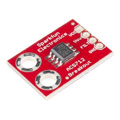
Figure 1. ACS712 Sparkfun breakout board
Usage
The ACS712 Sparkfun breakout board has two metal loops. The circuit under measurement must be broken by these loops, identically to the way a traditional ammeter is connected to a circuit. The conductor under measurement is electrically isolated from the MBED, and the ground of the MBED and the circuit under test should NOT be connected.
Wiring
| ACS712 Breakout | MBED | Circuit under test |
| Vcc | VU | |
| Vout | Analog pin (p18) | |
| FILT | 1nF capacitor to ground | |
| GND | GND | |
| + Loop | Positive side of wire | |
| - Loop | Negative side of wire |
A voltage divider, if used, should be connected from Vout to GND, with the MBED analog pin connected at the divider tap.

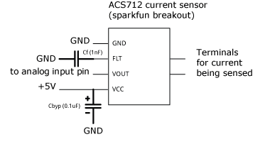
 Figure 2. ACS712 Hookup Schematic Figure 3. Wiring connections as used in the demo
The pin labeled "Filter" is connected to the output of the ACS712's first opamp. A 1nF capacitor connected between the "Filter" terminal and ground serves as a low pass filter, and shunts high frequency noise to ground. Different capacitance values will change the cutoff frequency of this simple low pass filter.
The ACS712 is a 5V device, and must be connected to the VU pin on the MBED.
The 5 amp version of the ACS712 has an output range of 1.5-3.4 volts. The MBED analog input has a range of 0-3.3V, therefore, the ACS712 should be used with a voltage divider in order to achieve the full range of values. However, if the maximum current value of 5A is not expected, the ACS712 5A version (and only the 5A version) can be used without a voltage divider.
The 20 and 30 amp versions of the ACS712 require a voltage divider in order to integrate with the MBED. The resistance ratio should be chosen to scale 5v to 3.3v, a ratio of 3.3/5.
AnalogIn limitations
The ACS712 outputs an analog voltage in response to current, simplifying integration with micro-controllers. However, analog input has limitations, specifically in circumstances where regular measurements are required.
The LPC1768 analog to digital converter has a maximum sampling rate of 200kHz. However, the AnalogIn class has a maximum sample rate of 50kHz due to overhead. As a result, the maximum frequency resolution of the ACS712 and LPC1768 will be 25kHz without accessing the ADC directly. Regardless of the polling method, the ACS712 has a maximum bandwidth of 80kHz and will not preform reliably above that threshold.
Voltage Dividers
Voltage dividers do exactly as their name describes, they divide voltage.
Any circuits text or website can provide more detail, but it must be noted that the resistance values should be as large as reasonable, as to lower the current draw on the output pin and ensure linearity in the output. Too low a resistance value will draw too much current, causing the ACS712's output to sag and giving a false reading. Resistors in the 100k range, such as 330k from Vout to the analog input with 510k from the input to ground, would serve well in this application.
ACS712 Library
The ACS712 library functions for the 5, 20, and 30 amp versions of the sensor. The user must identify both the type of the sensor and the voltage divider ratio, if any, used with the sensor.
Import program
Public Member Functions |
|
| ACS712 (PinName _pin, float voltDivRatio=1, short type=5) | |
|
Create a hall-effect sensor of the specified type.
|
|
| float | read () |
|
Read the value of the measured current in amps.
|
|
| operator float () | |
|
Read the value of the measured current in amps Allows the
ACS712
object to be used in a float context.
|
|
Demo
The Hello World example shown below does not use a voltage divider, and has Vout on the ACS712 connected directly to pin 18 on the MBED.
Import programACS712HelloWorldDemo
Demo of the ACS712 Library
The video below is an example of the Hello World Demo. The potentiometer on the right is part of an independent circuit, and varies current from 0 to 4 amps as the potentiometer sweeps along its range. The ACS712 sensing pads are in series with the potentiometer circuit.
The ACS712 is directly connected to the analog input on the MBED. As the current in the circuit varies, the MBED measures and reports the current value through USB serial to the operator, as seen in the terminal window.
Reference
The ACS712 datasheet is available (As of March 2016) at: https://www.sparkfun.com/products/8882
Please log in to post comments.
