Electric Mini Bike
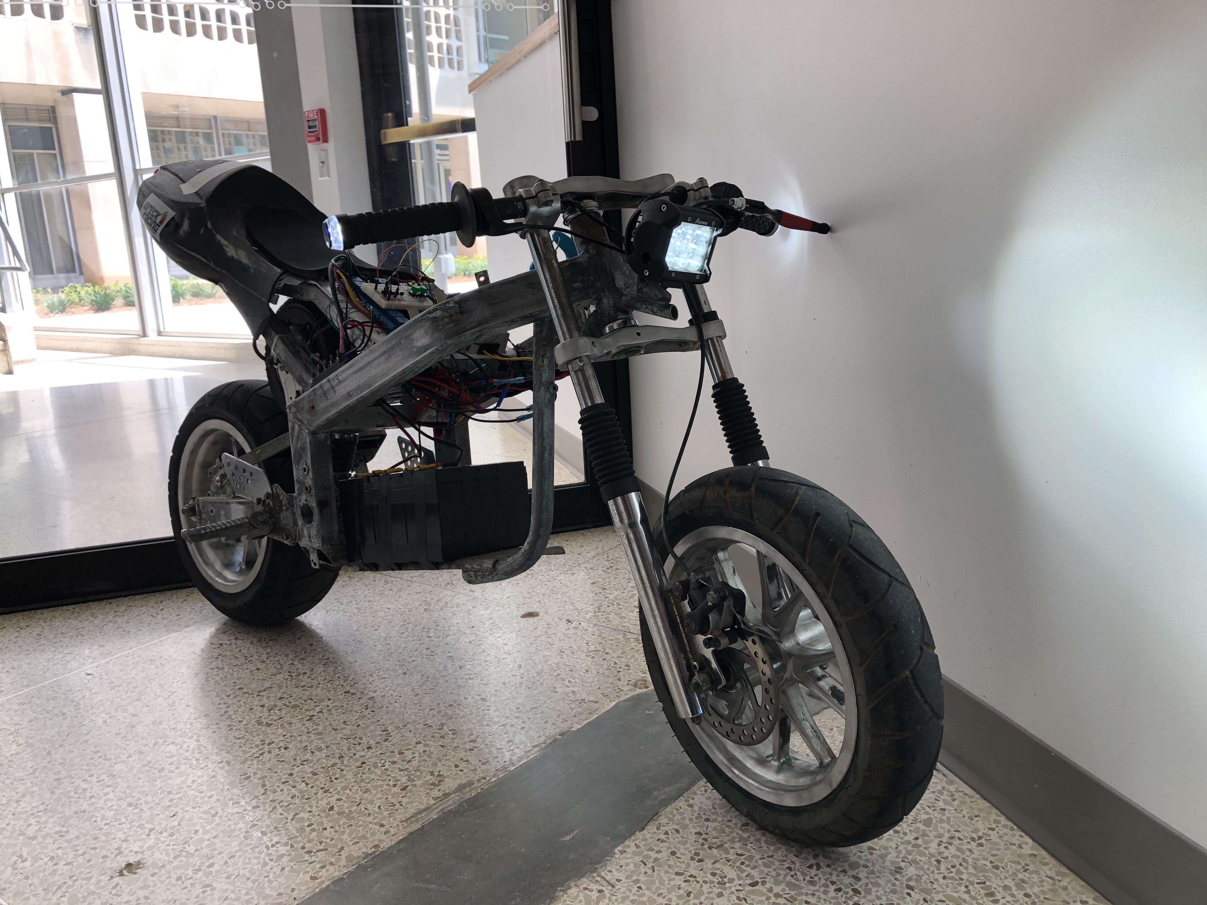
Description
The goal of this project was to create a brushless electric mini bike using a recycled hub motor and add features to make it street legal and easy to use. We used an MBED and a relay board to control the devices on the bike. The MBED measures battery voltage as well as speed and displays it on the uLCD screen. Auto headlights was created using a photo-resistor to measure the light and decide when to turn the lights on.
Demo
Components
- mbed!
- Relay Module
- 36V to 12V Converter
- Batteries
- Motor Controller
- Power Switch
- Brake Handle with Switch
- Potentiometer
- Headlight
- Blinker
- Brake Lights
- 36V Charger
- Charger port
- Proto Board
- Bread Board
- Push Buttons
mBed Pinout
Power
| Pin | Relay Board |
|---|---|
| VIN | 5V |
| GND | GND |
Inputs
| Pin # | Component |
|---|---|
| p5 | Brake switch |
| p6 | Left blinker switch |
| p7 | Right Blinker switch |
| p15 | 36V Battery Voltage |
| p16 | Photoresistor |
| p17 | RPM from Motor controller |
Outputs to Relay board
| Pin # | Component |
|---|---|
| p21 | Rear Right Blinker |
| p22 | Rear Left Blinker |
| p23 | Front Right Blinker |
| p24 | Front Left Blinker |
| p25 | Headlight |
LCD
| Pin # | Component |
|---|---|
| p9 | TX |
| p10 | RX |
| p11 | RST |
Note: The 5V from the relay board was used to power LCD and Ground goes to GND.
Code
Import programmbed_bike
4180 Electric Bike
- RTOS used to control monitoring and lighting threads
- Blinkers and brakes controlled simultaneously with a mutex lock
- Information displayed on uLCD screen
Hardware Setup
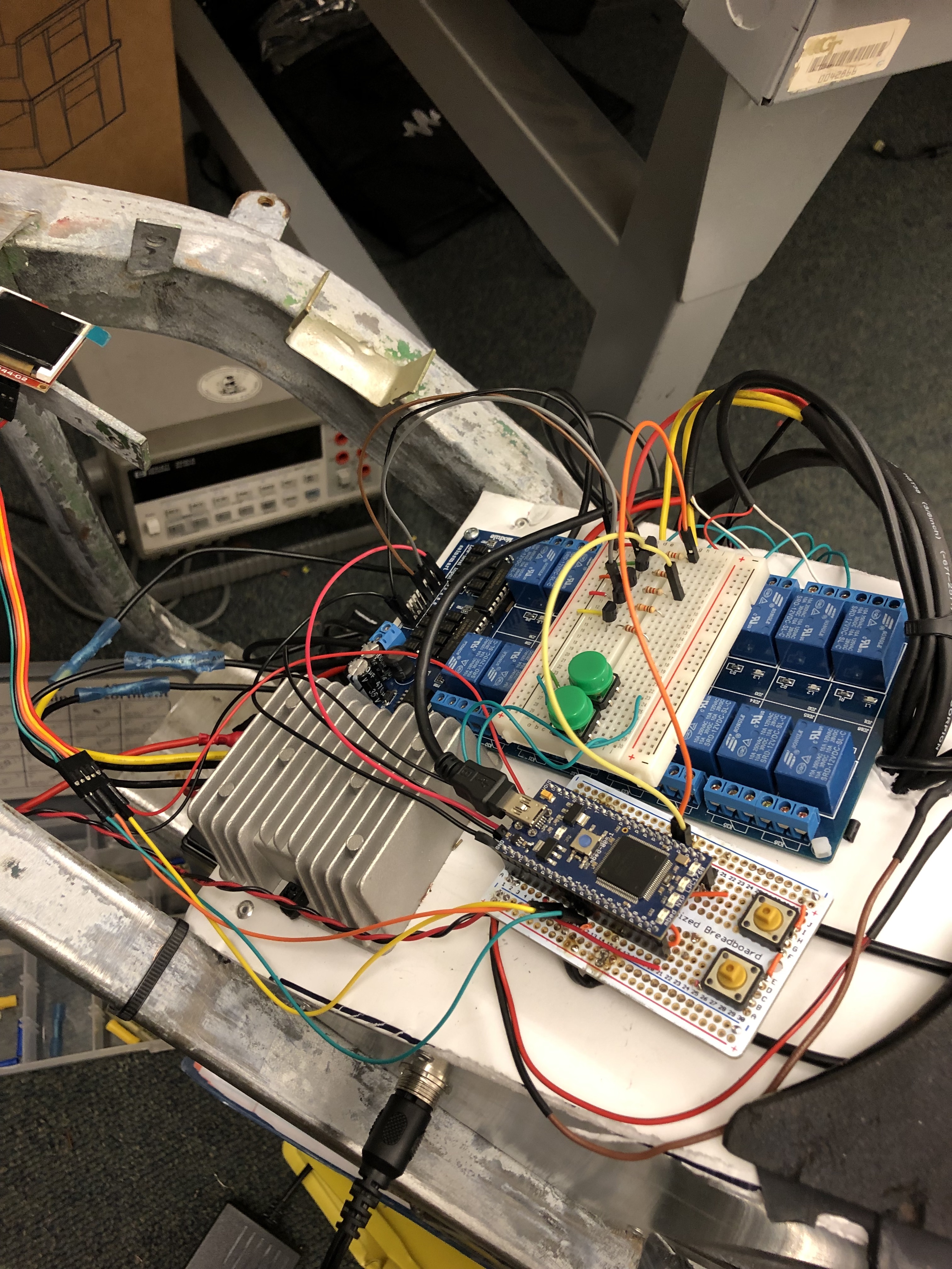
Push Buttons How to setup Pushbuttons
Using the Relay Board
The relay board is controlled by connecting its logic pins to the logic ground. Since the mbed is 3.3V logic and the relay board is 5V, transistors must be used. A 2N3904 was used for every control signal going to the relay board.
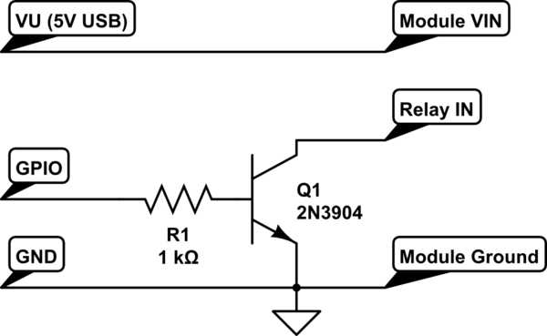
The relay board also needs 12V from the converter to drive the relays.
Motor Controller The Motor Controller has readily available documentation on the internet for how to wire.
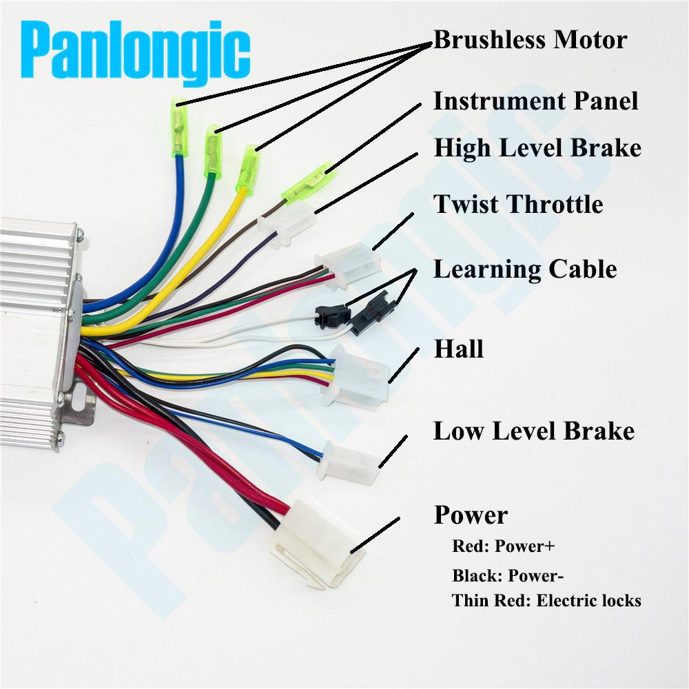
All of the security functions were ignored, power was wired directly to battery, and the "Electric Locks" was wired to the key switch.
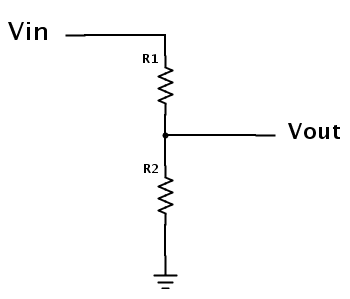
Battery Monitoring A simple voltage divider circuit was used to scale the 36V down to a measurable 3.3V signal. 10M ohm resistor used on the top end and 2 1 M ohm resistors in parallel on the bottom side.
LCD Screen

Wheel Mounting
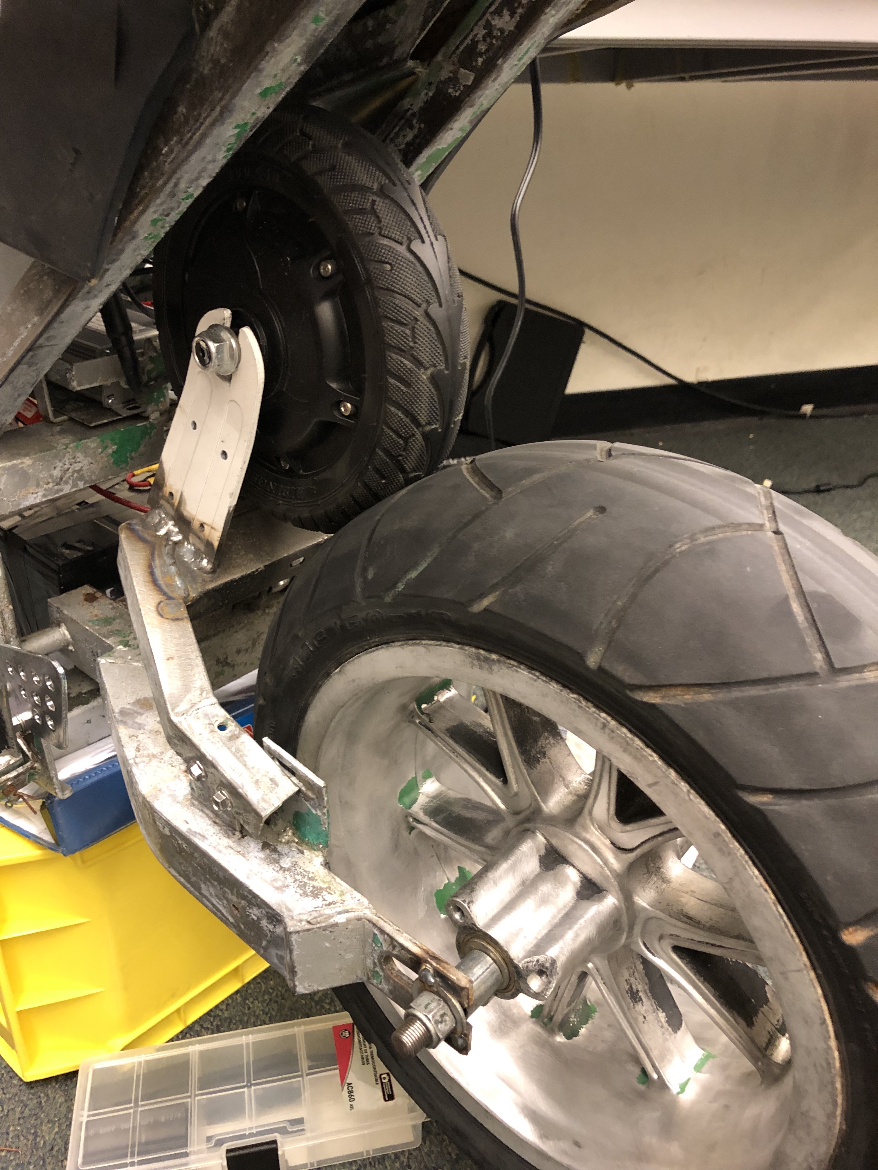
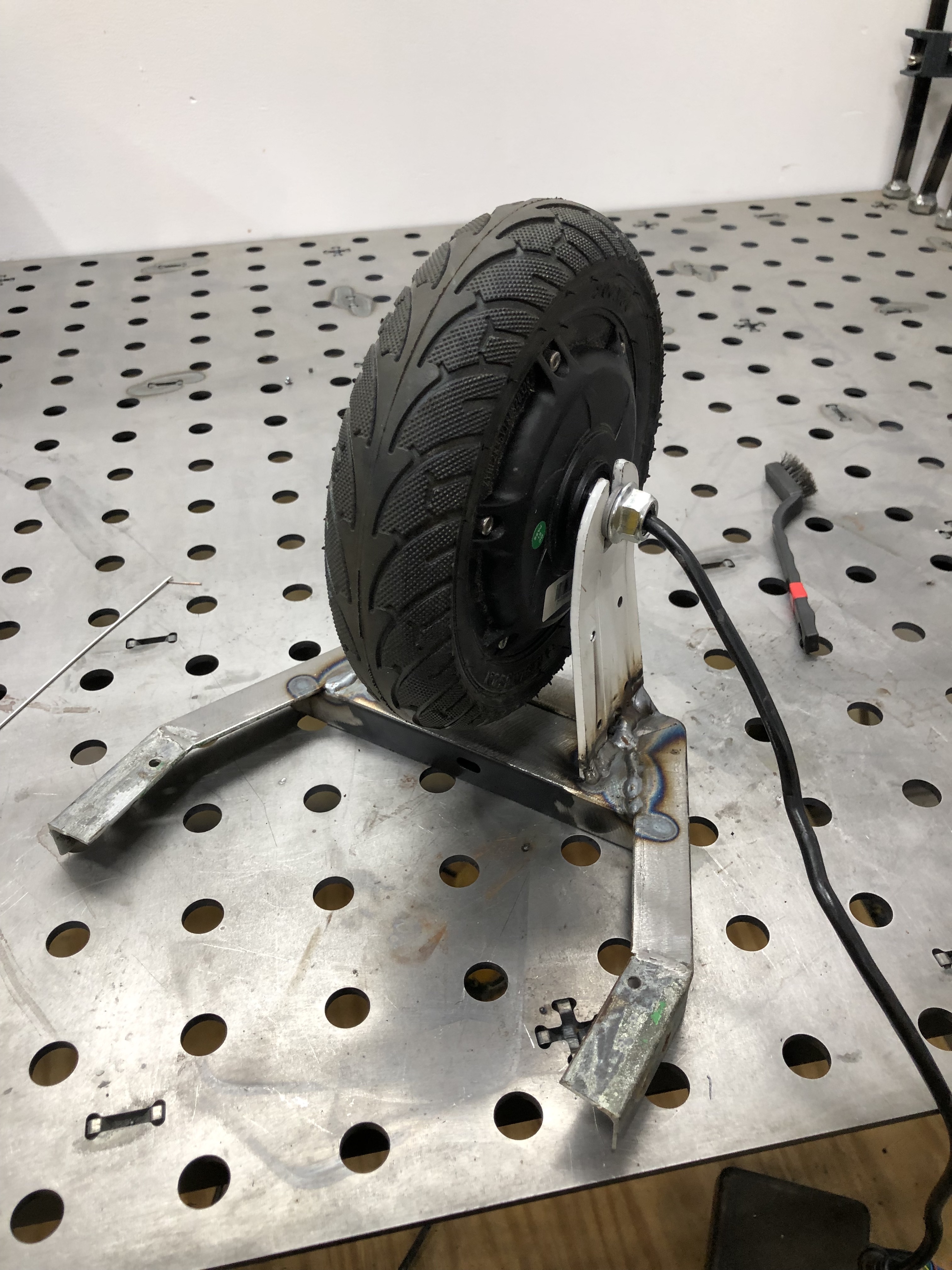 Tire is deflated to install and then re-inflated to allow them to not slip.
Possible Improvements
Throttle Control: Currently, the throttle is controlled by a 5v potentiometer connected straight to the motor controller. We tried reading the potentiometer in to the mbed and using PWM to output to the controller the desired speed. The motor controller became very glitchy and did not cooperate with PWM. The analog out pin only goes to 3.3V, so we did not bother testing that. Some sort of DAC converter could be used to convert the PWM signal to an analog voltage which might satisfy the controller. This would allow us to include more features in the bike.
Speed Reading: The RPM output signal was measured on an oscilloscope and found to be a 36v square wave PWM signal, but is very noisy. We made a voltage divider circuit using 2 10 Mohm resistors on the top and a 1 Mohm resistor to ground. This gave us a signal we could measure on the mbed, but it was still too noisy and the amplitude was too low. A better filtering circuit would allow the signal to be read much nicer.
Please log in to post comments.
