Home energy monitor
Page last updated
23 Apr 2011, by
 Daniel Peter
.
3
replies
I've had a go at a home energy monitor based on the mbed, measuring whole
house electricity and gas. This is done in a non-invasive way with a current
and voltage transformer for the electrical power and an IR photoreflector for
the gas.
Inspiration came from http://openenergymonitor.org/emon/ and
http://blog.richard.parker.name/2009/04/25/how-to-build-a-web-connected-gas-meter-with-your-arduino/
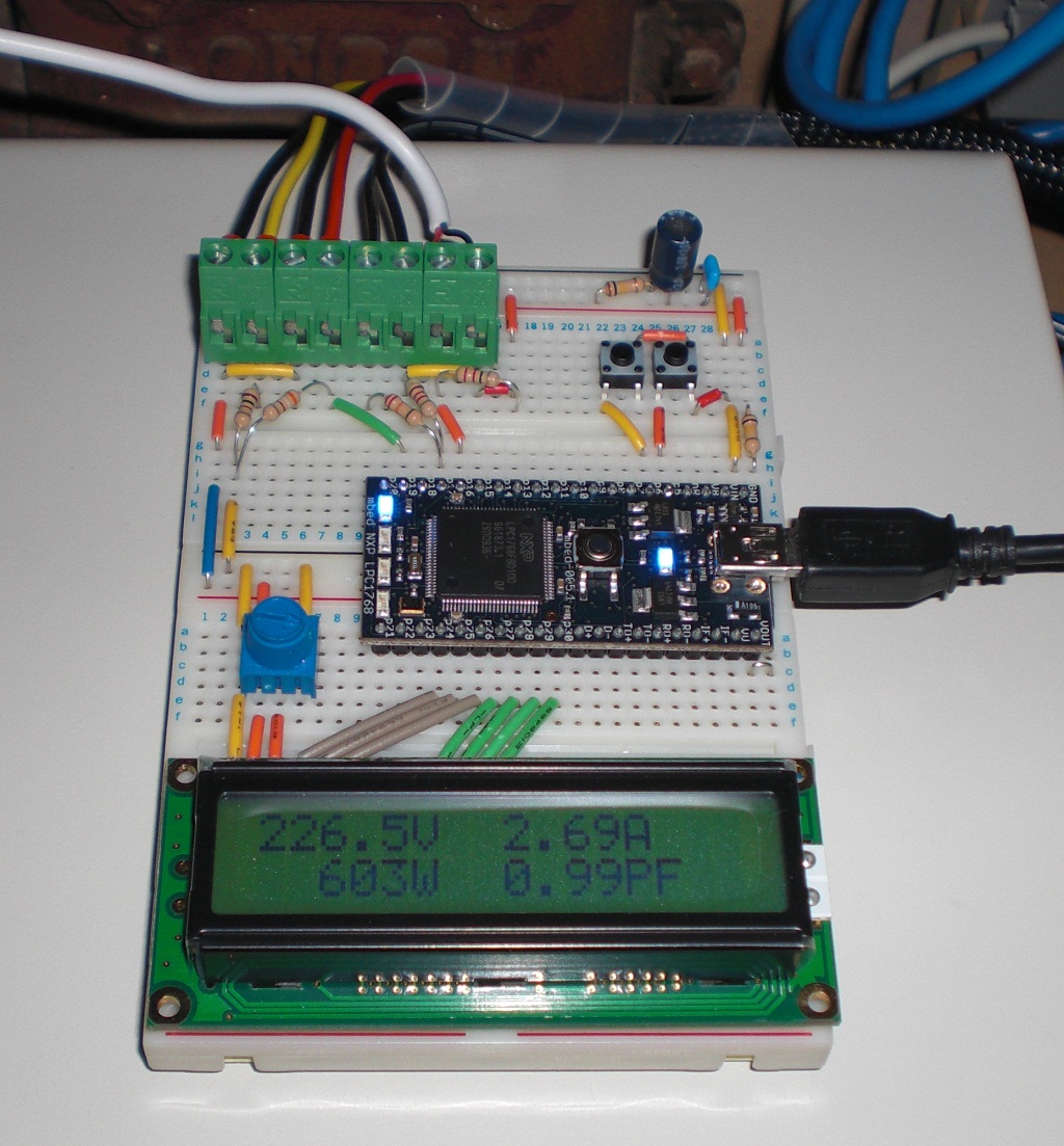
This picture shows the LCD displaying electrical power (one of the pushbuttons
is used to toggle to gas unit display at the moment):
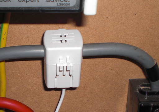
Current transformer (voltage transformer is not shown; it is an AC-AC plug-in
adapter):
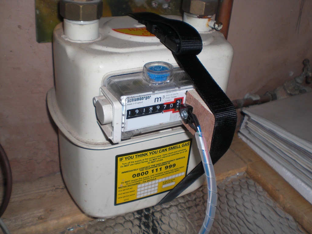
Photoreflector (the zero digit on the rightmost dial is conveniently
reflective):
Daniel,
Great project. Do you have a schematic of the photoreflector (Fairchild QRB1134 ?) connection to the Mbed.
Do you use InterruptIn, have you got debounce? I'm working on an energy datalogger. I've started with an RS485 connection to my solar invertor and I also want to measure electricity and gas.
Wim
Hi Wim
I'm using an AnalogIn sampled at 10 Hz, with software filtering applied to take out the spikes and then the pulse located using level crossing hysteresis. You could try doing that with a low pass filter in hardware instead - have a look at Rob's blog linked from this post.
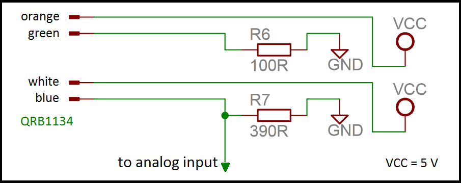
I think my wiring is as per the Arduino circuit, I just fiddled with the resister values to get a good discrimination between the reflective 0 and the rest of the digits on the meter.
Let me know if you want to see the code. If you want a circuit I can give you that as well but need to reinstall Eagle CAD first!
Regards
Daniel
Hi Daniel,
I am working on a similar project but using the MCP3909 metering chip. Could you please post a rough schematic of your project? Also, you mention that you are sampling the analog input (from the current transformer presumably) at 10 Hz - do you amplify this to 0..5V analog in range? Is 10 Hz sampling sufficient to determing RMS current and the phase shift?
Thanks a lot for any help!
Ganesh
#
09 Nov 2010 . Edited: 11 Nov 2010
Hi Ganesh
The discussion with Wim was about sampling the photoreflector (Fairchild QRB1134) for the gas readings (which is a based on a reflective digit in the meter every 0.01 m3 of gas).
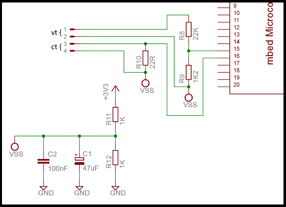
You are right to think that 10 Hz would not be sufficient for the electrical power measurement. I'm sampling at 500 Hz (10 samples per mains cycle) for that. I have a CT with a winding ratio of approx 1250 and a burden resistor of 22 ohm added to a voltage offset (1.65 V) into a 0 - 3.3 V analog range. For the voltage measurement, I have a VT with a winding ratio of 21 followed by a resistive voltage divider ratio of 16, again into the 3.3 V analog input with offset.
Regards
Daniel
Hi Daniel,
Thanks! Did you face any problem while measuring small currents (i.e. when the input from the CT is just few mV peak-to-peak)? I tried once with PIC uC and realised that the input was too noisy and that is why I was thinking about using an opamp and then an RMS converter before taking DC signal into the uC.
If you could share the schematics and program it would be of great help. I am doing an academic project wherein I am investigating construction of a simple power-meter for home appliication.
Cheers
Ganesh
PS: Your breadboard construction is really very nicely laid out !
Hi Ganesh
I'm sure there is noise there, I'm not doing any kind of filtering on the signal from the CT or VT. I calibrated my energy monitor against a plug-in type, and was happy it could measure power down to a couple of watts, which I was quite impressed with. You do need to keep the burden resistor and voltage offset components close to the analog input to avoid adding more noise in once you go from current to voltage on the CT.
Regards
Daniel
Hi Daniel,
Thanks for the detailed explaination. I am going to put a low offset OP amp for current measurement to amplify in the lower end of measurement. I will post the results as soon as I have tested it out.
Cheers
Ganesh
Do you have a schematic of the photoreflector (Fairchild QRB1134 ?) connection to the Mbed
Hi Wim
Here it is ... resistor values are going to depend to an extent on how reflective the target is. I set it up measuring voltages before going anywhere near the mbed.
Regards
Daniel
#
11 Nov 2010 . Edited: 11 Nov 2010
Do you want a tip?
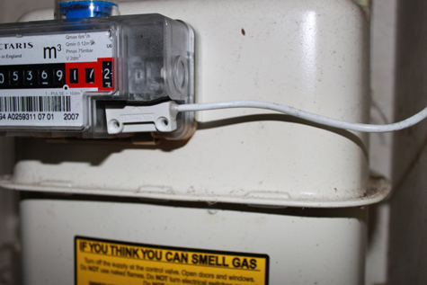
Get a door reed switch, cost about €1.00 and hold it up against the meter just about where your interrupter is.
Those meters come with a rotating magnet already installed and ready for remote monitoring :)
Do you want a tip?
Hi
My meter is an old Schlumberger one (pre 2001) rather than the more modern Actaris one like yours (2007), and doesn't have the cut out under the final digit to allow a reed switch to be mounted. It does have a reflective zero which works nicely with a photoreflector though ;-)
Thanks
Daniel
Hi Wim
Here it is ... resistor values are going to depend to an extent on how reflective the target is. I set it up measuring voltages before going anywhere near the mbed.
Regards
Daniel
Hi Daniel
Thanks for sharing your knowledge... I' ll give it a try.
Regards
Wim
Hi
Where did you get the current and voltage transformers? Can you do true RMS measurements?
Regards,
Networker
#
15 Dec 2010 . Edited: 16 Dec 2010
Hi
The current transformer is an Efergy eOne Sensor (looks to have been discontinued now but other similar types should be available, have a look at the parts list here).
The voltage transformer is a generic AC/AC plug in supply eg. 240 VAC down to 9 VAC.
I followed the theory here for calculating RMS current/voltage etc. If I was doing this again, I'd probably want to add something (eg. capacitor and ferrite bead) to the analog inputs - see this thread here. There is noise on the inputs, but since everything is averaged it doesn't cause too much of a problem in this application, and get still get a good range.
Regards
Daniel
Edit - Mischa has determined an RC low pass filter will work rather than using a capacitor and bead - see updated post here.
Hi, thanks,
well they look cheap enough, now I will try to get one for that price.
Regards,
networker
hi daniel,
How did you perform the high pass filter in software, i am doing a similar project but i am using different methods to obtain the current and voltage readings.
How did you handle the sampling? i still do not understand how the A/D converter on the MBED works, I understand that the Vref is 3.3v and a maximum tolerance of 5v, what if you use a diode, you still get values in the -ve domain, how does the mbed deal with this? I know you used DC biasing and sampled the entire waveform, but any feedback will be appreciated
Regards
Ed,
Hi,
I went online and did a bit of research, I found the mbed "missing manual" (a datasheet really) that gave me ALL the information i needed about the ADC plus more, if anyone is interested, here is the link, and another one for those who really want to understand the LPC17XX MCU
None of them mention MBED explicitly, its probably due to some red tape shenanigans on the NXP side. but it is indeed talking about the mbed.
I am still interested in knowing how to do the high pass filter in software, publishing your code will be a huge help Daniel.
Thanks
Search Results
3 comments on Home energy monitor:
(I'm in the UK with a nominal mains voltage of 240 V and frequency of 50 Hz)
With my simple power calculating code, I am seeing a power factor of around 0.75 with small resistive loads (incandescent lamp at 40 W) when I would expect near 1.00. I imagined this was due to a phase shift with the current transformer (CT), so I set about exploring this.
The graph below gives a cross correlation between voltage and current sampled at 2 kHz using various resistive loads. If the CT were perfect, the high point of all the curves would be at 0 samples on the x-axis.
Cross correlation code implemented in the mbed from http://paulbourke.net/miscellaneous/correlate/.
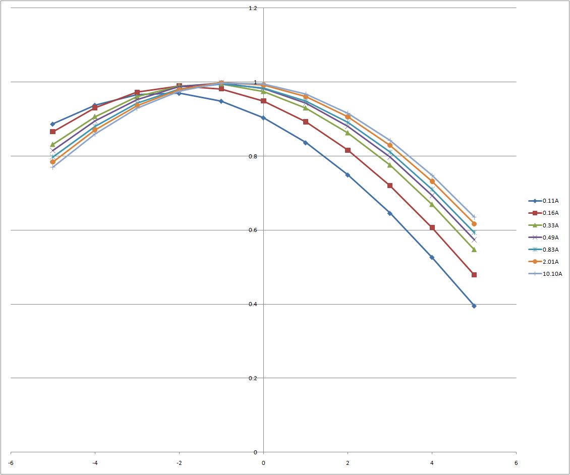
Using Excel LINEST function (http://spreadsheetpage.com/index.php/tip/chart_trendline_formulas/) and the Excel Solver add-in (http://archives.math.utk.edu/ICTCM/i/21/C006.html), I obtained the number of samples delay for each load (converted to degrees), to generate the following curve:
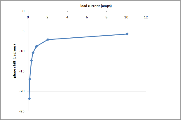
It's non-linear which apparently is expected due to magnetic saturation characteristics as a function of the excitation current in the transformer (http://www.crmagnetics.com/Portals/0/analysis_of_ct_error.pdf).
I've found a good paper (http://focus.ti.com/lit/an/slaa122/slaa122.pdf) with some ideas about how to correct this, so I'll see if I can improve the accuracy of my energy monitor at small loads and power factors away from unity (which will be more affected by phase shift).
Without any phase shift correction, I get the following results comparing my energy monitor with my Maplin plug in monitor:
Incandescent 40 W lamp:
Maplin 38 W, 1.00 PF
mbed 40 W, 0.75 PF
Halogen desk lamp with transformer:
Maplin 23 W, 0.90 PF
mbed 28 W, 0.57 PF
This is mainly an issue at lower loads. For comparison, a 300 W halogen lamp is much better (which is probably why I didn't pay too much attention to the issue originally):
Maplin 314 W, 1.00 PF
mbed 313 W, 0.99 PF
I have another issue to address which is that I've assumed a DC bias at exactly half the 3.3 V ADC range, and this is not the case (due to resistors not being identical). I'm not sure yet exactly what effect this has on the accuracy.
Daniel,
I'm new to MBED and to programing in general. I would like to measure current using an SCT-013 which looks to be similar to your setup. Is there any chance you would be able to share the code you have for this project or at least the portion for measuring the RMS voltage input?
Hi Daniel
Hope u are active now and help me as soon as possible !
I'm tryin to build a real time active energy meter using the IC ADE7754 which has SPI com and thru this spi im gonna read the values to the mbed 1768 board atleast thats what i thot. i wud really appreciate your help frm the bottom of ma heart and i wud like to hear your thots on my Idea .
Thanks.
Please log in to post comments.


Daniel,
Great project. Do you have a schematic of the photoreflector (Fairchild QRB1134 ?) connection to the Mbed.
Do you use InterruptIn, have you got debounce? I'm working on an energy datalogger. I've started with an RS485 connection to my solar invertor and I also want to measure electricity and gas.
Wim