IoT Amplifier with Digital Effects
With a quarter-inch input, mbed, Adafruit Bluefruit LE UART BLE breakout board, op amps, Class D Audio Amplifier, and speaker, it's possible to create a functional amplifier from the mbed with digital effects controlled from a smartphone app.
Project Block Diagram

Materials
- Complex Components
- MBED Microcontroller
- Adafruit Bluefruit LE Bluetooth Module
- Class D Audio Amplifier
- Speaker
- 3x TLV2462CP Operation Amplifiers (each has 2 op-amps built in)
- ¼ Inch Jack Adapter
- Guitar/Line level input
- Discrete Components
- Capacitors
- 2x 2.2nF
- 4.7nF
- 2x 0.1uF
- 47uF
- 470uF
- Resistors
- 2x 2.2kOhm
- 2.7kOhm
- 2x 47kOhm
- 2x 4.7kOhm
- 2x 10kOhm
- 500kOhm Potentiometer
- Capacitors
Quarter Inch Audio Jack
The quarter inch audio jack is a common standard for electric and bass guitars and passes voltage as converted from magnetic coil pickups situated in close proximity to a vibrating string. The frequency of the string vibration determines the pitch of the note, and the physical vibrations are interpreted as voltages for the purpose of reconstructing the sound waves after amplification. The typical monophone (monaural or mono) quarter inch jack features a sleeve ring and tip connection with posts for hot (+V) and ground wires. Stereo quarter inch jacks also exist and feature an extra +V post along side the hot and ground posts of the mono jack. Two hot leads allows for equivalent source level leads to be routed to separate speakers after amplification for identical signal reproduction in a stereo field.
Information
The AC voltages produced by the quarter inch jack are typically less than 1V peak-to-peak and centered about ground level, which can cause some issues with the mbed A-to-D converter truncating the negative voltages into a square wave on the ground level, causing a distorted output. While this could be desireable for certain music styles, producing a clean signal reproduction on the output will likely require a voltage biasing pre-amp circuit (see Bluetooth Amplifier with Effects section) to bring the full AC signal into the range of values the A-to-D converter can process.
Quarter Inch Instrument Cable
The typical delivery cable from instrument to amplifier is the quarter inch tip, sleeve plug for mono or tip, ring, sleeve for stereo connections. In the mono configuration, the tip serves as the positive connection while the sleeve serves as the negative (ground). In the stereo configuration, the tip and the ring serve as positive connections for each stereo channel, respectively, while the sleeve is the negative (ground).
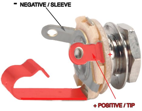
Quarter Inch Mono Jack with positive and negative terminals
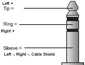
Tip, ring, sleeve cable for quarter inch stereo jack
Pre-amp Circuit
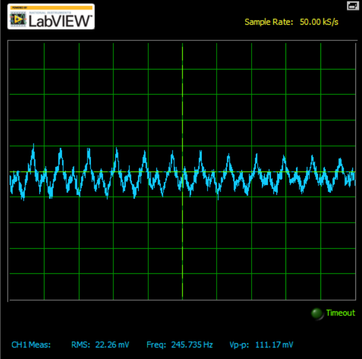
In order to ensure good sound quality, the small signal generated from the guitar must be amplified so that the ADC can pick up more detail from the sound wave. The waveform coming out of the quarter inch jack as captured by an oscilloscope is shown below:
Pre-Amplifier Circuit: Combined Stages
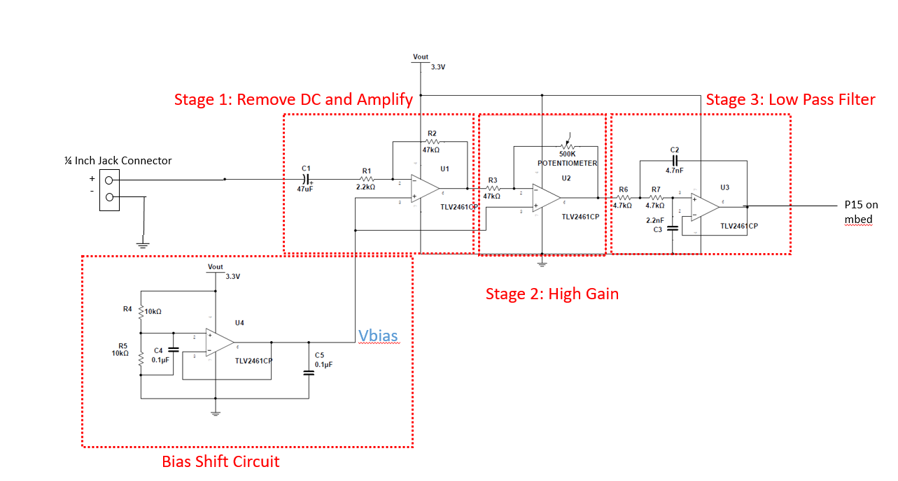
DC Bias Shift Circuit
As we can see, the signal is very small (100s of mVPP range) and it is also centered at 0 V. The MBED operating range for the analog input pins, however, is in the range of 0 to 3.3 V. Therefore, the signal must be amplified, in order to allow for better read resolution by the MBED, but it also must be shifted so that the entire signal lies within the range of 0-3.3V. We DC shift the signal by inputting a bias voltage into the positive terminals of the amplifier op-amps. This bias voltage is created by using a voltage-follower op-amp configuration. The input to the negative terminal of the op-amp is a simple 1:1 voltage divider, using the same value for both resistors of the divider circuit. This supplies a voltage of 3.3V/2 which is 1.65 V, which is exactly the middle of desired output range. Therefore, this allows maximum room within the specified range for a wave to be amplified. Using a voltage-follower configuration instead of a simple divider circuit ensures that the value received is determined by the two resistors, since a voltage-follower circuit has a theoretical input impedance of infinity, so no voltage drop occurs across the load (or op-amp). The output of this stage is supplied to the positive terminals of both the first and second stages of the amplifier circuit.
Pre-Amplifier Circuit Stage 1: Remove DC and Amplify
The first stage of the pre-amplifier circuit serves to remove any DC offset in the signal and provide amplification of the signal. This is accomplished using a high-pass filter in an inverting op-amp configuration. Using the equation for the cut-off frequency of a high-pass filter( Fc = 1/(2*pi*RC)), the cut-off frequency can be calculated as 1.54 Hz. This will not affect the range of audio desired, but will remove any DC offset. We can also calculate the gain of the circuit using the closed-loop voltage gain of an inverting amplifier, which is G = -R2/R1. In this case, R2 = 47k ohms and R1 = 2.2k ohms. Therefore the gain of this stage is approximately -21.
Pre-Amplifier Circuit Stage 2: High Gain
The next stage of the pre-amp circuit is to increase the gain. Similar to the first stage, this stage is an inverting op-amp configuration, without any filter components. In order to tune the circuit gain, a 500k ohm potentiometer is used as the second resistor. The potentiometer is necessary due to the peak-to-peak voltage variance of the audio signals. By including the resistive pot, the signal level can be adjusted. If the resistance is too low, then the signal is weak, diminishing volume and quality. If the signal is too large, voltages exceed Vdd and ground levels, squaring the wave and resulting in hard clipping and deteriorating sound quality. With the potentiometer, gain can be adjusted through a range of (0, -227). The ideal gain will lie somewhere between these values, likely towards the middle of the range.
Pre-Amplifier Circuit Stage 3: Low Pass Filter
The final stage of the amplifier is the Low Pass Filter stage. This is accomplished using a Sallen-Key LPF configuration. The Sallen-Key configuration is a non-inverting amplifier configuration, and has a cutoff frequency of (with resistor and capacitance labels corresponding to those in the diagram) fc = 1 / (2*pi * sqrt(R1*R2*C1*C2)). This results in a cutoff frequency around 10.5kHz. The gain of this circuit is 1.
Pre-Amplifier Circuit Output
After combining the stages, the signal will go from a small signal centered at 0 V, to a large signal (in the range of 0-3.3 V) centered at 1.65 V. The overall gain of the three stages ranges from 0 to 4,767 depending on the position of the potentiometer. The first two stages have a negative gain, and the third stage is a positive gain of 1, resulting in a positive output signal. The ouput of this stage goes to pin 15 on the mbed chip. The digital effects and volume control are implemented in code executed on the mbed platform.
The waveform of the pre-amp circuit output as captured by an oscilloscope is shown below:
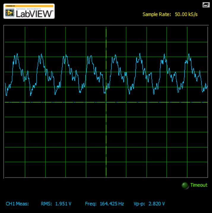
The resulting signal is clean (no clipping) and has a much larger Vpp value (2.82 V) than the input signal. It is also shifted so that the signal oscillates within the range of voltages that the mbed can read.
Output AC Coupling Circuit and Audio Amp with Speaker Output
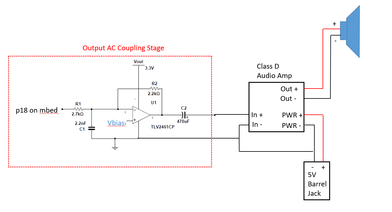
Once the signal processing has finished, the signal exits the mbed out of the analog output pin 18, and enters the output AC coupling stage, which serves to remove some of the noise that may affect the signal. The output of this stage then enters the Class D audio amplifier where the signal is amplified between 0-5V by using the 5V barrel jack adapter to power the amp. The 5V power allows for a louder signal. Also, the mbed is not actually able to supply enough power to drive larger speakers and needs an external power source. If the speaker was sufficiently small, it would not be necessary to drive the amp with external power, however the quality and level of sound would be diminished.
Full System Diagram
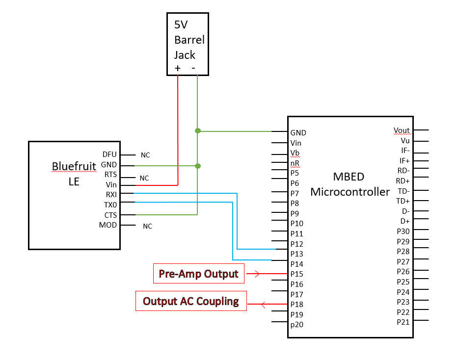
iOS Bluetooth Programming
The purpose of building the app was to bring the guitar amp to the 21st century by allowing control of certain effects through Bluetooth from an iPhone. This is done using a Bluetooth module connected to the mbed, which receives information from the app on the smartphone, allowing for wireless control of the amplifier effects. The majority of development time coding the iOS app was devoted to learning how to implement Bluetooth LE device communication with the iPhone. For ease of use, the app was built using Apple’s XCode environment that uses Objective C coding, which allows for similar building of GUI’s as windows C#. XCode allows the building of GUI’s through a visual interface, then programmatically controlling the GUI’s through their “ViewController” files. The implementation of the GUI’s as well as Objective C coding is well documented online, therefore the only topic this page will explain is getting the Bluetooth to work with the specific Bluetooth LE device.
iOS App Interface
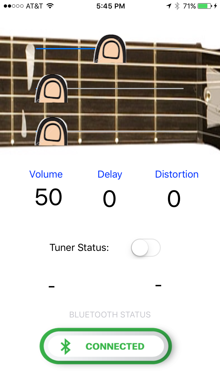
The application interface on the iPhone is shown below. The three fingers on the guitar neck are slider interfaces. The left end of the slider represents a value of 0, while the right end represents a value of 30 and where the finger is on the slider will determine the value. For ease of sending and receiving, values from 0 to 30 are sent from the first slider which corresponds to the volume, values of 31 to 60 are sent from the second slider which corresponds to the degree of digital delay added to the signal by the MBED, and values of 61 to 90 are sent from the third slider and corresponds to the degree of digital distortion added to the signal. These tiered values allow for easy interpretation on the MBED of which slider has changed value. These values are sent to the MBED through the Bluetooth implementation mentioned earlier in the format of an integer, so the MBED can easily read and rapidly change the corresponding digital effect based on the value sent across the Bluetooth connection. The labels below the guitar neck update to represent the current value of the corresponding slider represented as a percent. The tuner status section as mentioned earlier is not implemented in this iteration, though the app is designed for the future implementation as it has receiving of data implemented. On the bottom of the app, the Bluetooth status is displayed which will changed from “Disconnected” to “Connected” and vice versa.
The source code for the app is available via GitHub.
Bluetooth on iOS
Every Bluetooth device has UUIDs associated with specific functions on the device. For example, there are different UUIDs for the device address, as well as the TX and RX functions. A device may contain many different UUIDs that may not be relevant. For example if we wanted to build a device which only sends data to a Bluetooth device, then we would need the UUID for the device address as this would allow us to connect to the device, as well as the UUID for the TX because we wish to transmit, but the RX UUID would be irrelevant because we do not care about receiving data.
- For the Adafruit Bluefruit LE device, the UUID’s used in the app are:
- Service UUID: 6E400001-B5A3-F393-E0A9-E50E24DCCA9E
- TX: 6E400002-B5A3-F393-E0A9-E50E24DCCA9E
- RX: 6E400003-B5A3-F393-E0A9-E50E24DCCA9E
Information
Since the purpose of this project is an amplifier, only a brief overview of Bluetooth will be discussed. In general, the app begins the Bluetooth service by searching for a device with the Service UUID stated above. Once it finds it, it attaches a service to it and essentially connects. This process is fairly complex and has a lot of moving parts.
In the future, the goal is to implement a tuner function which can be read on the phone. Though the actual tuner function on the microcontroller portion has not been implemented, the app was designed with the future intent, and therefore is coded to also receive data. In order to receive data, the application must be told to look for the RX UUID and set up notification whenever something is received from the UUID. This is done in a similar way as simply connecting to the device.
If you are interested in an in depth and complex overview of Bluetooth on an iOS app, please refer to https://www.raywenderlich.com/73306/arduino-tutorial-integrating-bluetooth-le-and-ios
Sampling Rate
The Nyquist-Shannon sampling theorem defines the minimum sample rate for an analog to digital conversion that preserves all of the information in the original signal as twice the maximum frequency present in the signal of interest. For the purposes of analog to digital conversion of instrument signals, the commonly accepted sample rate is 44.1 kHz. This comes from the commonly stated range of human hearing being from 2 Hz to 20 kHz. 44.1 kHz is sufficiently more than the perceptible 20 kHz that it should preserve all perceivable information in an analog signal when converting to digital samples.
In the following code example the 23 us wait roughly corresponds to taking an input sample at a rate of 44.1 kHz.
( 1 / 44100 = 22.676 us )
mbed Amplifier Hello World
main.cpp
#include "mbed.h"

AnalogIn input(p15);
AnalogOut output(p18);

int main(void)
{
    while(1)
    {
        output.write(input.read()*100.00);
        wait_us(23);
    }
}
IoT Amplifier with Digital Effects mbed Code
The distortion effect is implemented as a simple overdrive distortion where the value is used to scale the samples, driving them toward clipping. The volume scaling works similarly, scaling the peak to peak voltage to approximate volume control.
Import programBluetooth_Amplifier_with_Effects
Simple mbed amplifier for quarter-inch audio input with volume, delay, and distortion control from smartphone app via bluetooth.
main.cpp
//Library includes
#include "mbed.h"
#include "rtos.h"

#define MAX_DELAY   10000   //Max size of delay effect sample buffer(too large can crash on compile from memory limit)

//mbed pin declarations

AnalogIn pot(p20);
DigitalOut led(LED1);
DigitalOut led2(LED2);
AnalogIn input(p15);
AnalogOut output(p18);
Serial pc(USBTX, USBRX);
Serial blue(p13,p14);

//global variable declarations

int inv_gain = 3;                       //scale factor for decreasing delay volume
int delay = 0;                          //store value for delay from smartphone app
float volume = .5;                      //store value for volume from smartphone app
float distortion = 1.0;                 //store value for distortion from smartphone app
unsigned short buffer[MAX_DELAY];       //declare array for storing samples for delay effect
int scaleFactor = 30;                   //global to convert int values from smartphone app sliders

/*******************************************************
 Bluetooth thread for reading input from smartphone app
********************************************************/
void threadBluetooth(void const *args)
{
         while(1)
         {
              if(blue.readable())                       //check if new value is available
              {
                   int changeVal;                       //variable to hold value from smartphone app
                   changeVal = blue.getc();             //get new value from app via bluetooth

                   if(changeVal <= scaleFactor)         //check if new value falls in volume slider range
                   {
                       //convert volume to float value in range [0.0-1.0]
                       volume = (float)changeVal/((float)scaleFactor+3);
                   }
                   else if(changeVal <= scaleFactor*2)  //check if value is in delay range
                   {
                       //convert delay to float in range (0.0 - 1.0]
                       delay = ((float)changeVal-((float)scaleFactor+1))/((float)scaleFactor)*MAX_DELAY;

                       if(changeVal == 31)              //if new value is bottom of delay slider
                       {
                           delay = 0;                   //set delay to zero (disable effect)
                       }
                   }
                   else if(changeVal <= scaleFactor*3)  //check if value is in distortion range
                   {
                        //convert distortion to float in range (3.0 - 4.0)
                        distortion = 3.0 + ((float)changeVal-(2*(float)scaleFactor+1))/((float)scaleFactor);

                        if(changeVal == 61)             //if new value is bottom of distortion slider
                        {
                            distortion = 1;             //set distortion to one (disable effect)
                        }
                   }
        }
        Thread::wait(100);
}                                                       //end bluetooth thread

/*****
 Main
*****/

int main(void)
{
    Thread threadBlue(threadBluetooth);                 //startup Bluetooth thread for smartphone app
    int oldDelay;                                       //global for delay comparison

    while(1)
    {
        int i;                                          //for loop count variable

        if(delay > 0)                                   //check if delay effect is on
        {
            if(delay != oldDelay)                       //if delay value has changed re-buffer
            {
                for (i = 0; i < delay; i++)             //buffer loop
                {
                    buffer[i] += input.read_u16();
                    oldDelay = delay;
                }
            }
            while(delay > 0)                                        //while delay is on
            {
                buffer[i] = buffer[i]/inv_gain + input.read_u16();  //scale buffer value and add to input
                output.write_u16(distortion * volume * buffer[i]);  //write to output
                i = (i+1) % delay;                                  //traverse buffer array(use delay number of values)
            }
        }
        else
        {
            //with no delay write input value scaled by volume and distortion
            output.write_u16(distortion * volume * input.read_u16());
            wait_us(23);                                             //wait time based on sample rate
        }
    }
}                       //end main
Library Functions for loT Amplifier with Digital Effects
Import librarymbed-rtos
Official mbed Real Time Operating System based on the RTX implementation of the CMSIS-RTOS API open standard.
IoT Amplifier with Digital Effects Demo Video
Please log in to post comments.
