Important changes to repositories hosted on mbed.com
Mbed hosted mercurial repositories are deprecated and are due to be permanently deleted in July 2026.
To keep a copy of this software download the repository Zip archive or clone locally using Mercurial.
It is also possible to export all your personal repositories from the account settings page.
You are viewing an older revision! See the latest version
Homepage
I used a header board for an STM MEMS evaluation kit in order to take a look at some common MEMS sensors:
LPS301: Pressure and temperature sensor LG3D20: Gyroscope LSM303DLHC: Accelerometer and magnetometer
The header was an STEVAL-MKI124V1 which is designed to work with an STM motherboard evaluation system. I took a shortcut and used it with an LPC1768 MBED over I2C
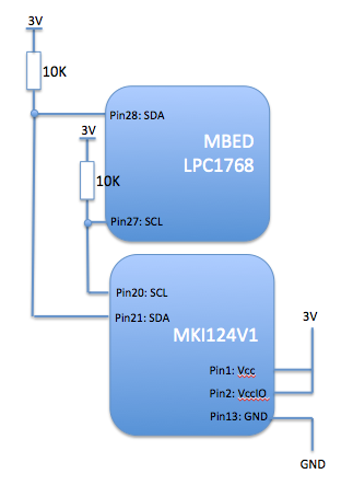
Hook-up was trivial:

The schematic is here:
http://www.st.com/web/en/catalog/tools/PF253482
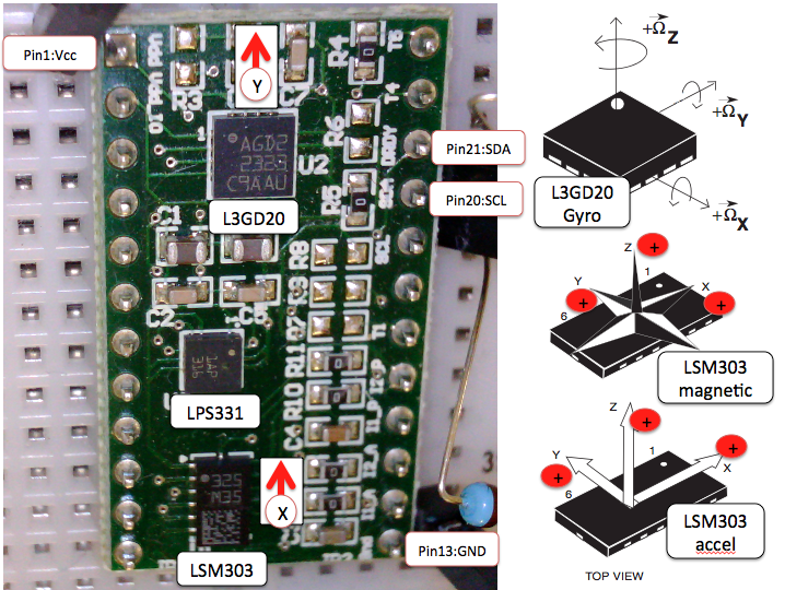
The orientation of the sensors on the board is like this:

The code sets up each of the sensors and then provides a continuous output of temperature, pressure and orientation. Rather than optimize for performance or efficiency, the code here is intended to show clearly how to access the sensors.
An interesting twist was to use the linear accelerometer to find the vector of the earth's gravitational field (i.e. down) and to use that to make a tilt-adjusted compass.
The sensors do need some calibration. Here is a scatter plot of the raw output of X and Y values from the magnetometer:

The chart should be a perfect circle around the origin (allowing for distortion on Excel charting).
Blue points are the raw data Red is offset-corrected Green is offset and soft-iron corrected
As you can see, there is an offset error but also and X:Y ratio term. The latter is a soft iron error and is well described in a great article here: