IR Sensor Detection Robot

Introduction
The Key idea of this project is to utilize the Infrared sensor to detect the wall, and instruct robot to make correct turning direction. The IR sensor has 3.3V voltage supply, ground and output between 0 to 3.3V base on the distance it detects. Here is the link to the data sheet about specific IR sensor we used in this project: http://www.sharp-world.com/products/device/lineup/data/pdf/datasheet/gp2y0a21yk_e.pdf According to the distance voltage relationship from this data sheet and AnalogIn Read from mbed, we can detect if there is obstacle in front of robot moving path or not. However, in order to cover full range of robot moving path direction, at least three IR sensors needed. If implemented in this way, not only has to add more IR sensors, but also increase the mbed processing power. Because mbed has to constantly checking the AnalogIn read from three of IR sensors. A good way to solve this is to add just one servo, and mount the single IR sensor on the bracket and attach to the servo. Constantly swing the servo to look around situation. Once the IR sensor detect certain obstacle in certain distance, it will change the movement of the robot. For example, if IR detect obstacle is on the right, it will turn left; if IR detect obstacle on the left, it will turn right; it IR detect obstacle directly in front, it will back up and turn right.
Limitation
Because sensitivity of the IR sensor, it will get really close to the wall to detect the obstacle. So, it will hit the wall first and look around and find best movement solution.
Wiring
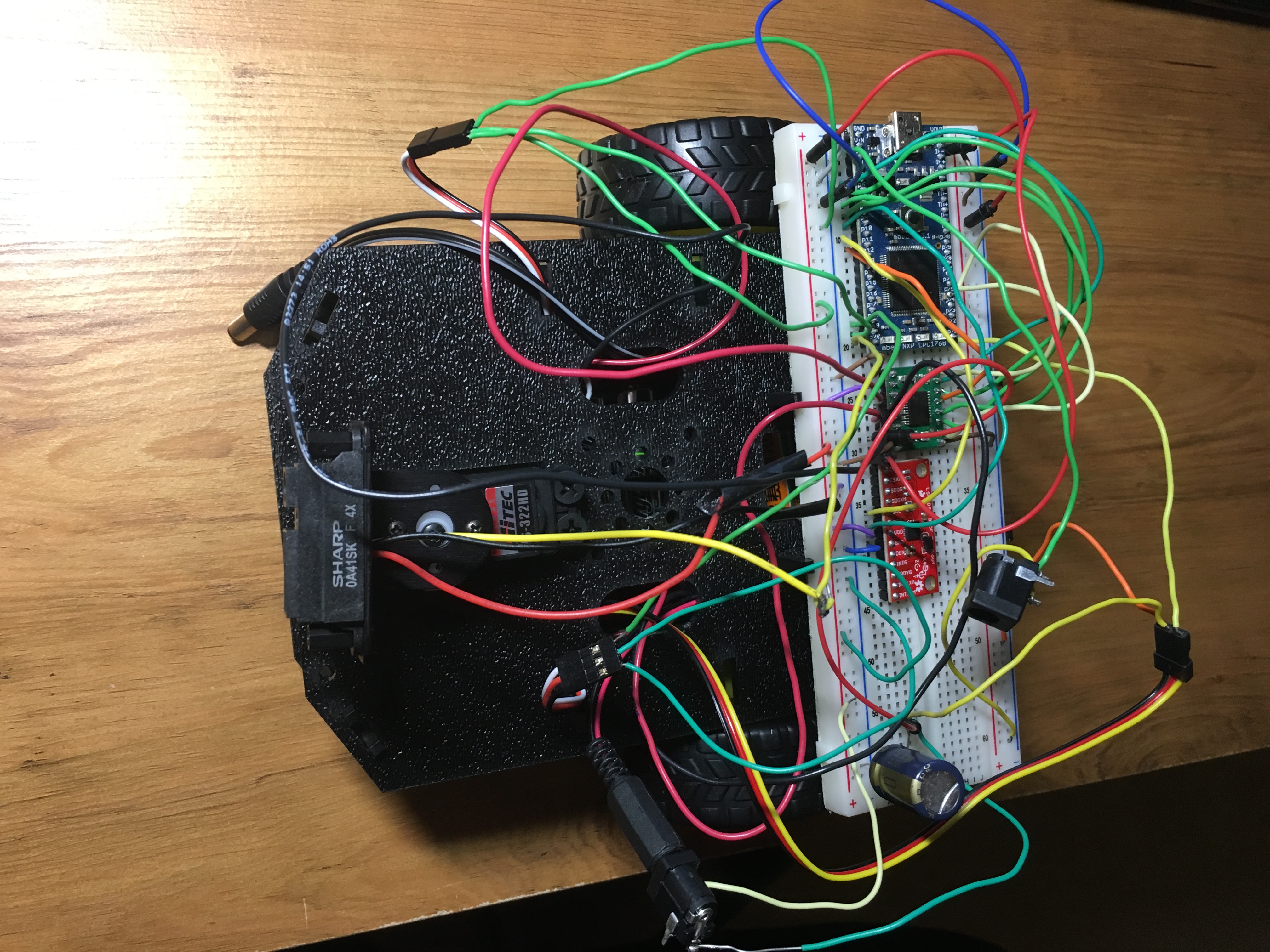
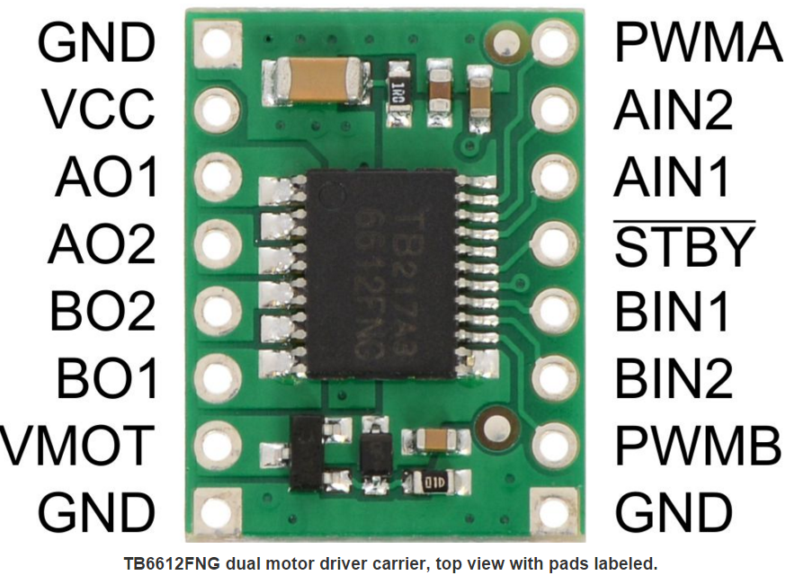
In total, there are three things need to connect to the mbed. H-Bridge chip(Control the power and speed of the motor), servo(swing the IR sensor) and IR sensor(Distance detection).

| MBED | H-Bridge | Motor | H-Bridge |
|---|---|---|---|
| GND | GND | Right Motor(BLK) | A01 |
| VOUT | VCC | Right Motor(RED) | A02 |
| p24 | PWMA | Left Motor(BLK) | B02 |
| p25 | PWMB | Left Motor(RED) | B01 |
| p11 | STBY |
And for VMOT, it should be connect to battery power supply 6.0V. Decoupling Capacitor can be used here between battery power supply and Ground.
| MBED | IR-Sensor | MBED | Sevo |
|---|---|---|---|
| GND | GND(BLK) | GND | BLK |
| VOUT | RED | p21 | Yellow |
| P20 | Yellow | Connect Red to the battery power supply 6.0V |
Also, another battery pack should supply power to MBED, positive to VIN, negative to GND.
Code
main.cpp
// Hello World to sweep a servo through its full range

#include "mbed.h"
#include "Servo.h"
#include "Motor.h"
#include "LSM9DS0.h"

// SDO_XM and SDO_G are pulled up, so our addresses are:
#define LSM9DS0_XM_ADDR  0x1D // Would be 0x1E if SDO_XM is LOW
#define LSM9DS0_G_ADDR   0x6B // Would be 0x6A if SDO_G is LOW

// refresh time. set to 500 for checking the Data on pc.
#define REFRESH_TIME_MS 500

LSM9DS0 imu(p9, p10, LSM9DS0_G_ADDR, LSM9DS0_XM_ADDR);//IMU, read the compass value.
Serial pc(USBTX, USBRX);//Only use this during the testing phase for pc debug.
Motor MR(p25, p6, p5); // Motor A pwm, fwd, rev
Motor ML(p26, p7, p8);//Motor B pwm, fwd, rev
DigitalOut STBY(p11); // Set STBY = 1, enable both motor; Set STBY = 0; disable both motor.
Servo myservo(p21);//PWM control for Servo
AnalogIn IR(p20); //IR sensor
AnalogIn LeftEncoder(p19);

//Return direction from servo - left, right or front
enum DIRC{LEFT,RIGHT,FRONT};

//Control Motor to turn right.
void TurnRight()
{

      ML.speed(-0.3);
      MR.speed(0.3);
      wait(2.1);

}

//Control Motor to turn left.
void TurnLeft()
{

      ML.speed(0.3);
      MR.speed(-0.3);
      wait(2.1);

}

//Control Motor to go forward.
void Forward()
{
    ML.speed(-0.55);
    MR.speed(-0.5);
    wait(0.01);
}

//Control Motor to Backup.
 void Backup()
{
     ML.speed(0.55);
     MR.speed(0.5);
}

//Control the servo to TurnLeft.
DIRC LookLeft()
{
    myservo = 0.0;
    wait(1);
    return LEFT;
}

//Control the servo to TurnRight.
DIRC LookRight()
{
    myservo = 0.9;
    wait(1);
    return RIGHT;
}

//Control the servo to LookStraight.
DIRC LookStraight()
{
    myservo = 0.5;
    wait(1);
    return FRONT;
}

int main() {

     STBY = 1;//enable both Motor
     wait(1.0);
     DIRC looking_dir;

    while(true)
    {
        Forward(); //Constantly go straight if there is no obstacle.


        while(1)//Control servo swing left and right, obtain IR value.
        {
            looking_dir = LookStraight();
            if(IR>0.6) break;
            looking_dir = LookLeft();
            if(IR>0.6) break;
            looking_dir = LookRight();
            if(IR>0.6) break;

        }

        //Base on IR value, make correct movement.
        if(looking_dir == FRONT)
        {
            Backup();
            wait(2.0);
            TurnRight();
        }
        else if(looking_dir == LEFT)
        {
            Backup();
            wait(2.0);
            TurnRight();
        }
        else
        {
            Backup();
            wait(2.0);
            TurnLeft();
        }
    }
}
Program
Import programLab4_Robot_Project_1
This Lab4 Robot Car Project.
Video
Future Work
As we can see from the video, the robot will hit the wall first and then start to look around. This is because once the servo swing, the voltage output from IR sensor change. If create some kind of thread to hold the previous value from IR sensor and do the movement, this problem can be solved. Also, IMU on the bread can be utilized as compass to make the turning more accurate.
Please log in to post comments.
