Final Project
Wiring
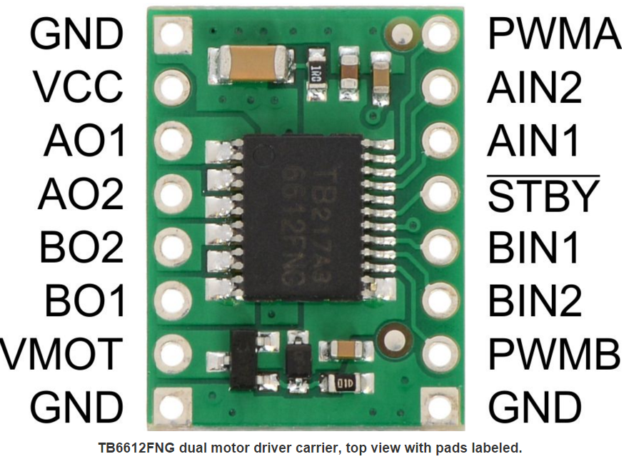
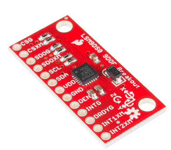
Two embed chips are needed for this project. One is used for the controller, another one is used for the robot car. For controller, three components connect with embed. There are a single push button(control stop or continue), a IMU chip(use accelerometer to detect the angles), and a Xbee chip(for sending command to robot car). For robot car, two components connect with embed. There are a H-bridge chip(Control the power and speed of the motor) and a Xbee chip(for receiving command from controller). Two Xbee adapters are need for inserting Xbee chip in both Robot car and Controller.


Robot Car Wiring
| MBED | H-Bridge | Motor | H-Bridge | MBED | Xbee |
|---|---|---|---|---|---|
| GND | GND | Right Motor(BLK) | A01 | GND | GND |
| VOUT | VCC | Right Motor(RED) | A02 | VOUT | VCC |
| p25 | PWMA | Left Motor(BLK) | B02 | p10 | DOUT |
| p26 | PWMB | Left Motor(RED) | B01 | p9 | DIN |
| p12 | STBY | p11 | RST | ||
| p5 | AIN2 | ||||
| p6 | AIN1 | ||||
| p7 | BIN1 | ||||
| p8 | BIN2 |
And for VMOT, it should be connect to battery power supply 6.0V. Decoupling Capacitor can be used here between battery power supply and Ground. Also, another battery pack should supply power to MBED, positive to VIN, negative to GND. An switch can be add to turn on and turn off the embed of the robot car.
Controller Wiring
| MBED | IMU | MBED | Xbee | MBED | Push Button |
|---|---|---|---|---|---|
| GND | GND | GND | GND | GND | FIRST PIN |
| VOUT | VDD | VOUT | VCC | p8 | SECOND PIN |
| p27 | SCL | p10 | DOUT | ||
| p28 | SDA | p9 | DIN | ||
| p11 | RST |
Please log in to post comments.
