MUTT mbed enabled robot vehicle
What Is It?
An attempt to make my mbed board mobile!
This page is intended to serve as a guide to anyone who's looking to get started but not sure where to.
Getting Started (MUTT v1)
As a first foray I wanted to use quite a bit of off-the-shelf kit and get something up and running quickly. Here's my shopping list
- FRDM-KL46Z. I've been using this for other mbed projects.
- Headers to connect the shield to the KL46Z. I've already soldered headers on, but as they're not included in the FRDM-KL46Z out-of-the-box, it's worth mentioning them.
- Chassis kit (various others are available)
- Arduino Motor Shield
- E18-D80NK infrared obstacle sensor & mounting bracket
- Jumper wires & batteries
Issues
The KL46Z doesn't support HW PWM on the 'PWM B' channel on the shield
PTD6 which is connected to the input to control motor 'B's speed can't be set up as a PwmOut. I've borrowed PTA5 (which can and is not used by the shield unless you attach to the TinkerKit headers) and connected it up to PTD6 via a jumper
5V supply
The motor shield supplies VIN (from the batteries) to the KL46Z, so the processor can be powered from this (that's good!). Unfortunately the KL46Z only supplies the 3.3V connection to the shield (which doesn't seem to be used), it doesn't supply the 5V connection unless powered by USB (that's bad!). Temporary work-around is to use a 5V USB power pack (I'm using a Power Bee just because I have one to hand ) - the same thing that many people use as a portable top-up charger for their smart 'phones.
Steps
Build the chassis
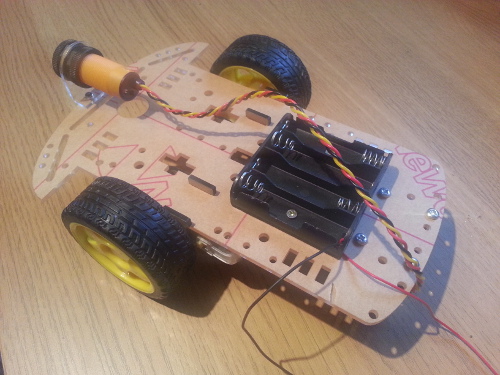
Connect shield to KL46Z
Battery To The Shield
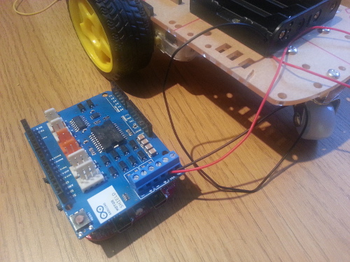
You *must* ensure that you get the battery connections the right way round. 'Vin' (as marked on the screw terminal on the shield) is +ve, taken from the red wire. 'GND' is -ve, taken from the black wire.
PTA5 to PTD6 (see issues, above)
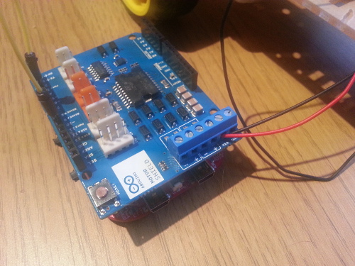
IR sensor to 5V, GND and A4
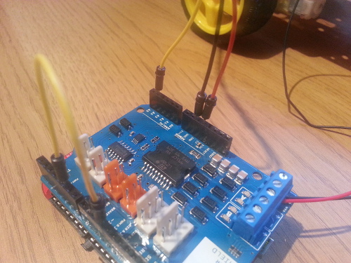
I used A4 as it's not used by the shield. schematics suggest that A5's also free.
Shield to motors
Code, Mark 1
The first "application" is intended to be very simple and just prove out the hardware. The application drives the vehicle forwards until the collision sensor detects that there's an object in the vehicle's path at which point it stops and waits for the obstacle to move.
Import programMUTTv1
First (and very, very simple) controller program for the MUTT. See http://mbed.org/users/johnb/notebook/mutt-mbed-enabled-robot-vehicle/
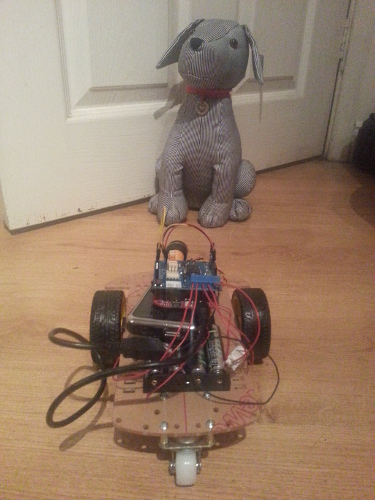
In the above photo, MUTT encounters Blake (a different type of mutt) and a face-off ensues. (Yeah, I know the wiring needs sorting out ...)
Future?
- Tidy up the wiring
- More advanced application
- Use the braking capability of the motor controller
- Monitor the current sensing feedback for the motors
- Refine the power supply
- An HC-SR04 ultrasonic range finder - The infra red obstacle detector will be relegated to the rear of the vehicle and a range-finder will be added to the front to allow smarter navigation.
- HMC5883L 3 axis digital compass - Better orientation awareness & feedback
- Wheel speed sensors
- XBee - Allow MUTT to talk to the world.
Please log in to post comments.
