SparkFun 9 Degrees of Freedom IMU - LSM9DS1
*NOTE: The readings are not accurate. However, the library can successfully read data from the IMU*
Introduction
The LSM9DS1 is a versatile, motion-sensing system-in-a-chip. It houses a 3-axis accelerometer, 3-axis gyroscope, and 3-axis magnetometer – nine degrees of freedom (9DOF) in a single IC! Each sensor in the LSM9DS1 supports a wide range of…ranges: the accelerometer’s scale can be set to ± 2, 4, 8, or 16 g, the gyroscope supports ± 245, 500, and 2000 °/s, and the magnetometer has full-scale ranges of ± 2, 4, 12, or 16 gauss.
Overview
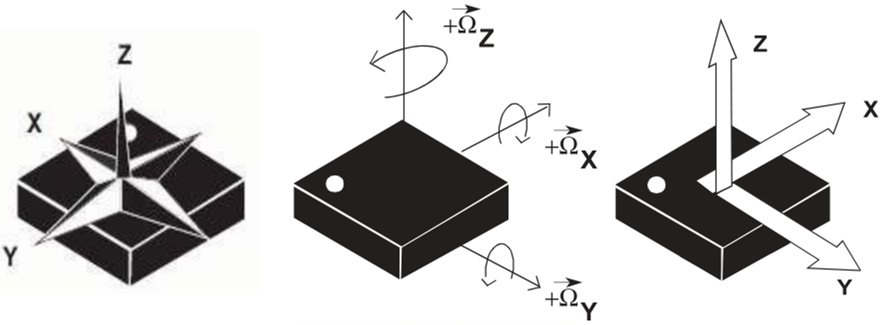
The LSM9DS1 can measure three key properties of movement – angular velocity, acceleration, and heading.
The LSM9DS1 measures each of these movement properties in three dimensions. That means it produces nine pieces of data: acceleration in x/y/z, angular rotation in x/y/z, and magnetic force in x/y/z.

SPI or I2C
In addition to being able to measure a wide variety of movement vectors, the LSM9DS1 is also multi-featured on the communication interface end. It supports both SPI and I2C.
The Serial Data Out (SDO) pin for example, does just that for SPI mode, but if you’re using the device over I2C it becomes an address selector. The chip select (CS_M and CS_AG) pins activate SPI mode when low, but if they’re pulled high the device assumes I2C communication.
Pinout
 The LSM9DS1 allows for either an SPI or I2C interface
SPI
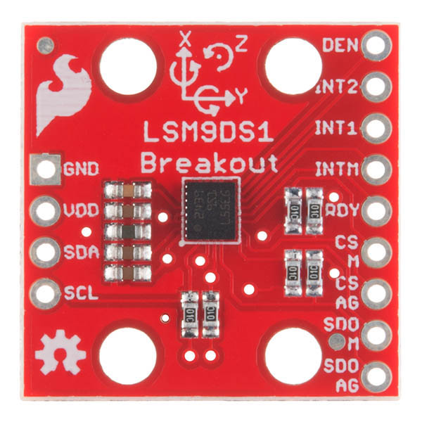
| Pin Label | Pin Function | Notes |
|---|---|---|
| DEN | Gyroscope Data Enable | Mostly unknown. The LSM9DS1 datasheet doesn't have much to say about this pin. |
| INT2 | Accel/Gyro Interrupt 2 | INT1 and INT2 are programmable interrupts for the accelerometer and gyroscope. They can be set to alert on over/under thresholds, data ready, or FIFO overruns. |
| INT1 | Accel/Gyro Interrupt 1 | Same as above |
| INTM | Magnetometer Interrupt | A programmable interrupt for the magnetometer. Can be set to alert on over-under thresholds. |
| RDY | Magnetometer Data Ready | An interrupt indicating new magnetometer data is available. Non-programmable. |
| CS M | Magnetometer Chip Select | This pin selects between I2C and SPI on the magnetometer. Keep it HIGH for I2C, or use it as an (active-low) chip select for SPI. HIGH (1): SPI idle mode / I2C enabled. LOW (0): SPI enabled / I2C disabled. |
| CS AG | Accel/Gyro Chip Select | This pin selects between I2C and SPI on the accel/gyro. Keep it HIGH for I2C, or use it as an (active-low) chip select for SPI. HIGH (1): SPI idle mode / I2C enabled LOW (0): SPI enabled / I2C disabled. |
| SDO M | SPI: Magnetometer MISO I2C: Magnetometer Address Select | In SPI mode, this is the magnetometer data output (SDO_M). In I2C mode, this selects the LSb of the I2C address (SA0_M) |
| SDO AG | SPI: Accel/Gyro MISO I2C: Accel/Gryo Address Select | In SPI mode, this is the accel/gryo data output (SDO_AG). In I2C mode, this selects the LSb of the I2C address (SA0_AG) |
I2C
| Pin Label | Pin Function | Notes |
|---|---|---|
| GND | Ground | 0V Voltage |
| VDD | Power Supply | Supply voltage to the chip. Should be regulated between 2.4V and 3.6V. |
| SDA | SPI: MOSI I2C: Serial Data | SPI: Device data in (MOSI) I2C: Serial data (bi-directional) |
| SCL | Serial Clock | I2C and SPI serial clock. |
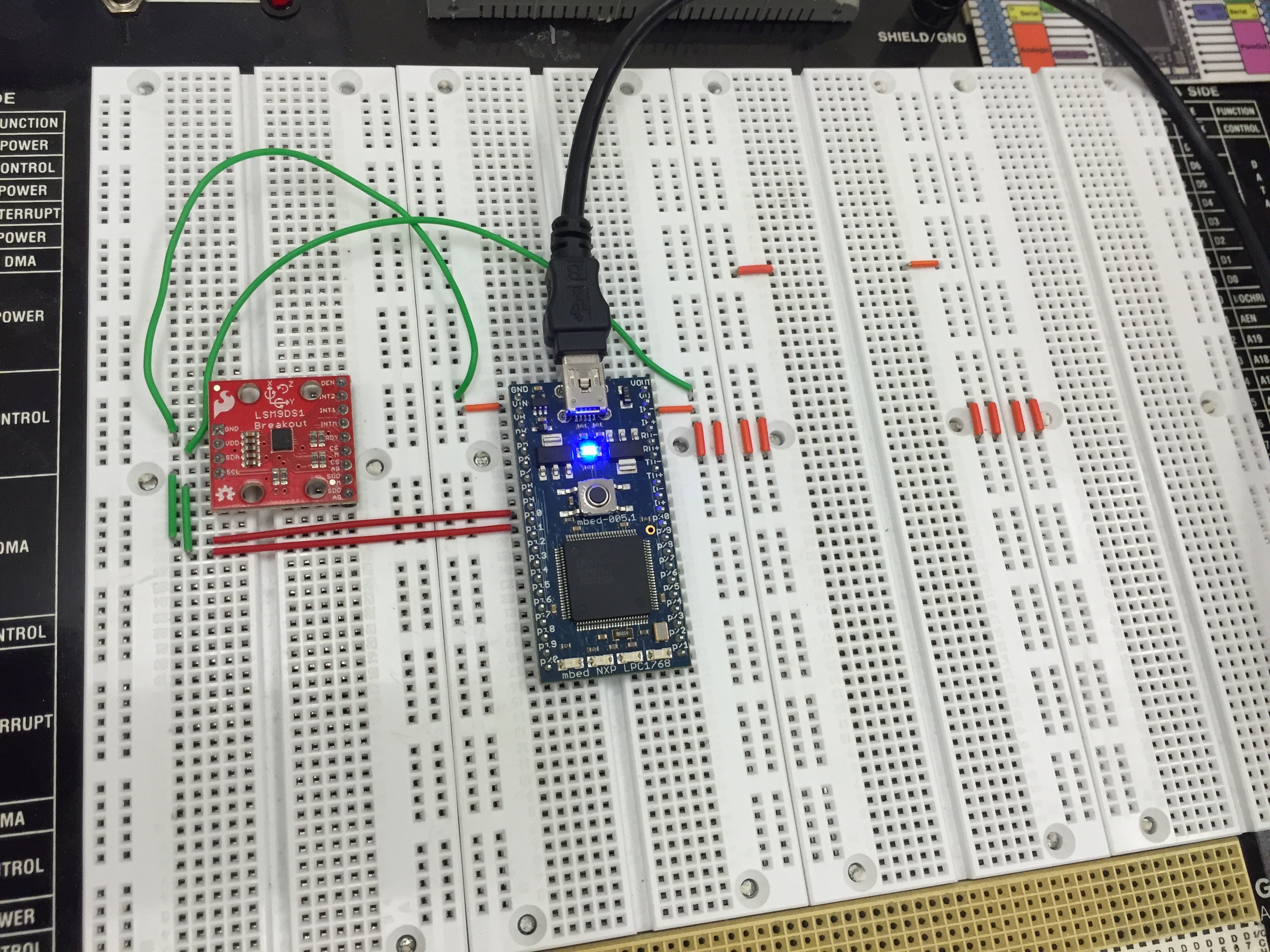
THIS IMAGE SHOWS I2C WIRING

How to Wire the Breakout to the Mbed
I2C
| Pin on Breakout | Pin on Mbed |
|---|---|
| GND | GND |
| VDD | Vout |
| SDA | p9 (SDA) |
| SCL | p10 (SCL) |
SPI
| Pin on Breakout | Pin on Mbed |
|---|---|
| GND | GND |
| VDD | Vout |
| SDA | p11 (MOSI) |
| SCL | p13 (SCLK) |
| CSAG | Any DigitalOut |
| CSM | Any DigitalOut |
| SDOM | p12 (MISO) |
API
Basic constructor and functions
/**
*Constructor for I2C
**/
LSM9DS1(PinName sda, PinName scl, uint8_t xgAddr, uint8_t mAddr);

/**
*Initialize the gyro, accelerometer, and magnetometer.
*This will set up the scale and output rate of each sensor.
**/
uint16_t begin();

/**
*Read the gyroscope output registers.
*This function will read all six gyroscope output registers.
*The readings are stored in the class' gx, gy, and gz variables. Read
*those _after_ calling readGyro().
**/
void readGyro();

/**
*Read the accelerometer output registers.
*This function will read all six accelerometer output registers.
*The readings are stored in the class' ax, ay, and az variables. Read
*those _after_ calling readAccel().
**/
void readAccel();

/**
*Read the magnetometer output registers.
*This function will read all six magnetometer output registers.
*The readings are stored in the class' mx, my, and mz variables. Read
*those _after_ calling readMag().
**/
void readMag();

/**
*Convert from RAW signed 16-bit value to degrees per second
*This function reads in a signed 16-bit value and returns the scaled
*DPS. This function relies on gScale and gRes being correct.
*Input: A signed 16-bit raw reading from the gyroscope.
**/
float calcGyro(int16_t gyro);

/**
*Convert from RAW signed 16-bit value to gravity (g's).
*This function reads in a signed 16-bit value and returns the scaled
*g's. This function relies on aScale and aRes being correct.
*Input: A signed 16-bit raw reading from the accelerometer.
**/
float calcAccel(int16_t accel);

/**
*Convert from RAW signed 16-bit value to Gauss (Gs)
*This function reads in a signed 16-bit value and returns the scaled
*Gs. This function relies on mScale and mRes being correct.
*Input: A signed 16-bit raw reading from the magnetometer.
**/
float calcMag(int16_t mag);
Code
Import libraryLSM9DS1_Library
IMU LSM9DS1 Library
Sample Program to use IMU through I2C printing to Serial COM
#include "LSM9DS1.h"

DigitalOut myled(LED1);
Serial pc(USBTX, USBRX);

int main() {
    LSM9DS1 imu(p9, p10, 0xD6, 0x3C);
    imu.begin();
    if (!imu.begin()) {
        pc.printf("Failed to communicate with LSM9DS1.\n");
    }
    imu.calibrate();
    while(1) {
        imu.readTemp();
        imu.readMag();
        imu.readGyro();

        pc.printf("gyro: %d %d %d\n\r", imu.gx, imu.gy, imu.gz);
        pc.printf("accel: %d %d %d\n\r", imu.ax, imu.ay, imu.az);
        pc.printf("mag: %d %d %d\n\n\r", imu.mx, imu.my, imu.mz);
        wait(1);
    }
}
Demo
More Information
Please log in to post comments.
