Home made mbed board with STM32F103VET6 microcontroller
Since nowadays there are STM32F103VET6 chips available for about 5$ a piece (e.g. on eBay) , I decided to build a low cost minimal mbed board which can be easily used for custom projects.
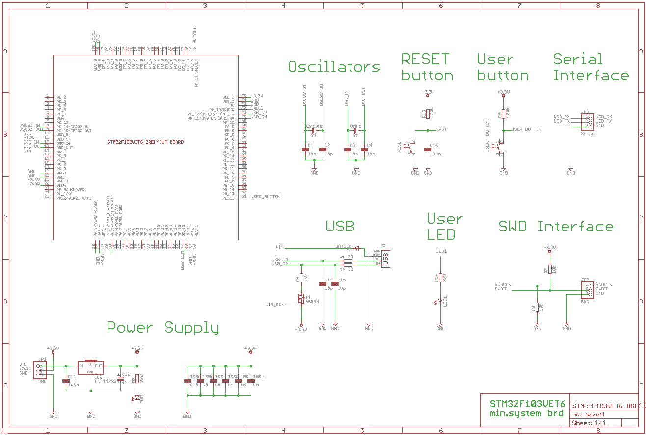
Schematic
It is not mandatory to install all parts. The USB interface, the User LED, the User button or the Serial connector can be omitted if you do not need them for your particular project.
Assembling the board
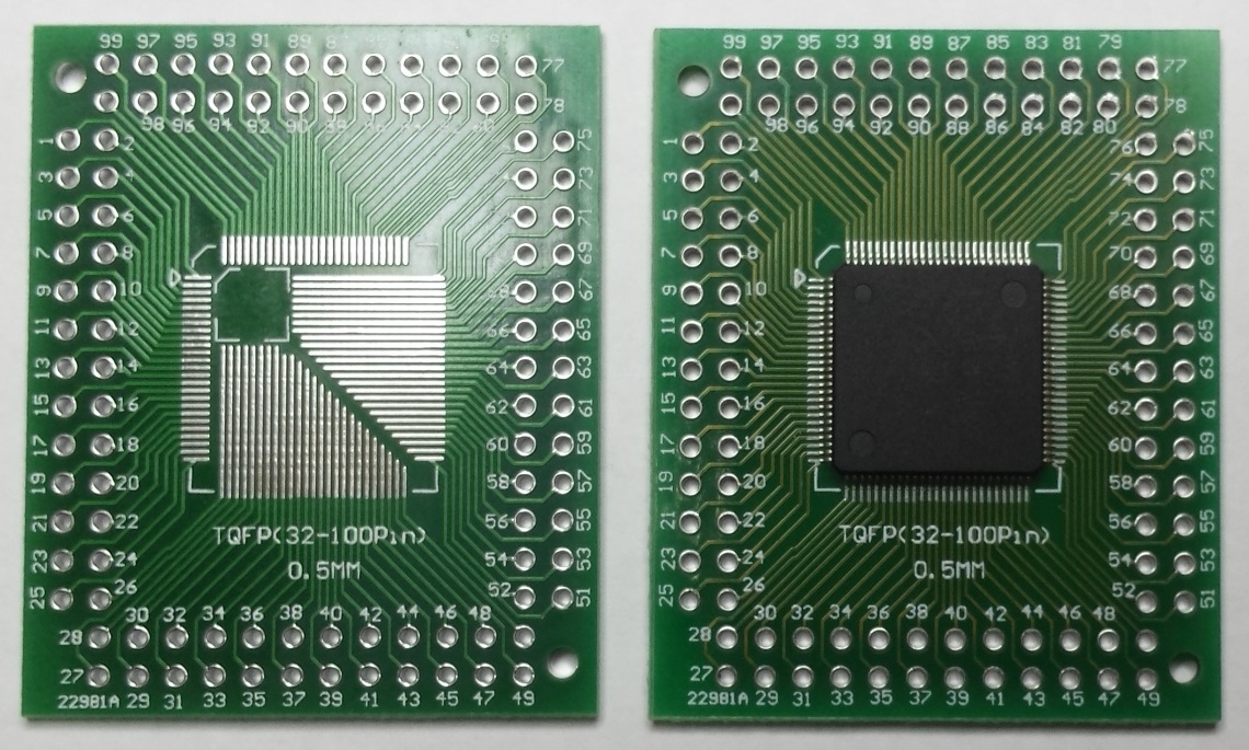
The biggest challenge was to build a 0.5mm pitch PCB and to solder an STM32F103VET6 onto such board. A low cost "TQFP100 to DIP" breakout board (e.g. this one) came to my rescue. For the base board I decided to design a single-layer PCB which can be built at home (e.g. with toner transfer method).
- Stick the STM32F103VET6 chip to the "TQFP100 to DIP" breakout board by applying glue just to the central part while avoiding the pins. Since it takes some time to precisely align the pins I do not recommend to use glue which hardens too quickly.
- Once the glue has been hardened (next day) solder the STM32F103VET6 to the board (by applying a plenty of soldering flux).
The "TQFP100 to DIP" breakout board before (on left) and after (on right) installing an STM32F103VET6 chip
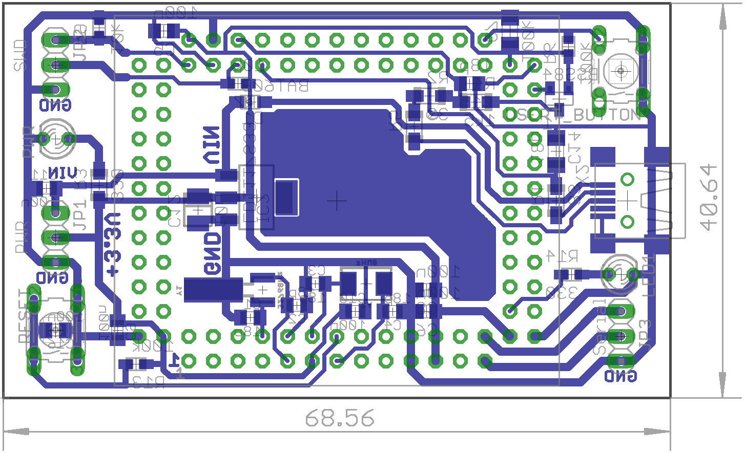
- Build a single layer PCB for the base board, for instance by utilizing the toner transfer method, according to this Eagle CAD project.
The single-layer base board - the size of smallest package is 0805

Programming
You can use the NUCLEO virtual disk to program the STM32F103VET6 board (drag and drop programming). To do that, an additional NUCLEO board is needed (any type equipped with ST-LINK/V2-1 will do).
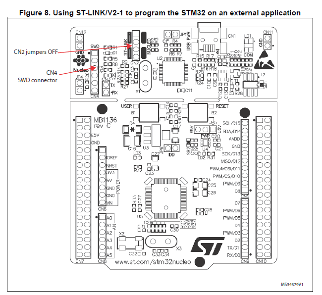
- Remove the two jumpers from the CN2 connector as illustrated in Figure 8:

- Connect the NUCLEO board CN4 connector to the STM32F103VET6 board using flying wires as follows:
| NUCLEO board CN4 connector | STM32F103VET6 debug connector | |||
|---|---|---|---|---|
| SWCLK | <=> | SWCLK | ||
| GND | <=> | GND | ||
| SWDIO | <=> | SWDIO | ||
- Provide power for the STM32F103VET6 board through a 3.3V pin, 5V pin or over a USB cable.
- Connect the NUCLEO board to your PC over a USB cable.
- To program the STM32F103VET6 board, click on the Compile button and save the binary to the NUCLEO virtual disk .
For more details have a look at the User Manual, chapter 6.2.4 Using ST-LINK/V2-1 to program and debug an external STM32 application.
Modifications to MBED library
To get 512kB Flash, 64kB SRAM, UART4, UART5, SPI3 and 80 GPIO pins:
- Since MBED pages do not allow to upload files with
zipextension,pngis used instead. To download target_nucleo_f103ve.zip right-click on the link and selectSave link as.... Once saved to your local drive, change the extension frompngtozipand unzip. - Replace the corresponding files in the
mbed-dev/targets/TARGET_STM/TARGET_STM32F1/TARGET_NUCLEO_F103RBfolder of your project with files you have downloaded.
4 comments on Home made mbed board with STM32F103VET6 microcontroller:
Please log in to post comments.


Hi Zoltan,
Thank you for your notebook.
How can I get STM32F103VET6 to use mbed for more pins and more falsh than STM32F103RBT6?
QT