Home made mbed board with LPC1768 microcontroller
The classic mbed board based on the NXP LPC1768 microcontroller, with a 32-bit ARM Cortex-M3 core running at 96MHz and featuring 512KB FLASH and 32KB RAM, is one of my favorits. Since not all the features are aways needed and nowadays there are LPC1768 chips available for about $5 a piece (e.g. on eBay) , I decided to build a low cost minimal mbed board which can be easily used for custom projects.
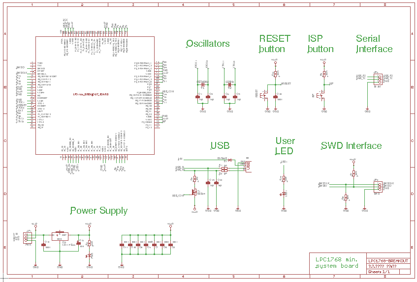
Schematic
It is not mandatory to install all parts. The USB interface, the User LED, the SWD connector or the Serial connector can be omitted if you do not need them for your particular project or for the possibility to program the chip by both methods (see below).
Assembling the board
The biggest challenge was to build a 0.5mm pitch PCB and to solder an LPC1768 onto such board. A low cost "TQFP100 to DIP" breakout board (e.g. this one) came to my rescue. For the base board I decided to design a single-layer PCB which can be built at home (e.g. with toner transfer method).
- Stick the LPC1768 chip to the "TQFP100 to DIP" breakout board by applying glue just to the central part while avoiding the pins. Since it takes some time to precisely align the pins I do not recommend to use a glue which hardens too quickly.
- Once the glue has been hardened (next day) solder the LPC1768 to the board (by applying a plenty of soldering flux).
The "TQFP100 to DIP" breakout board before (on left) and after (on right) installing an LPC1768 chip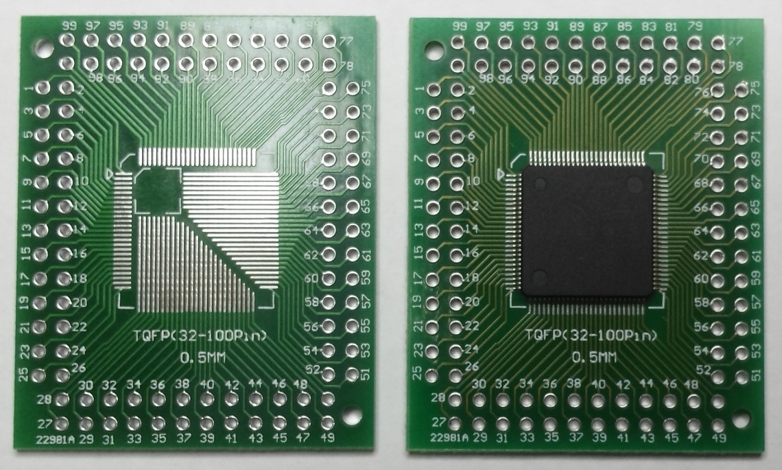
- Build a single layer PCB for the base board according to this Eagle CAD project.
The single-layer base board (The size of smallest package is 0805)
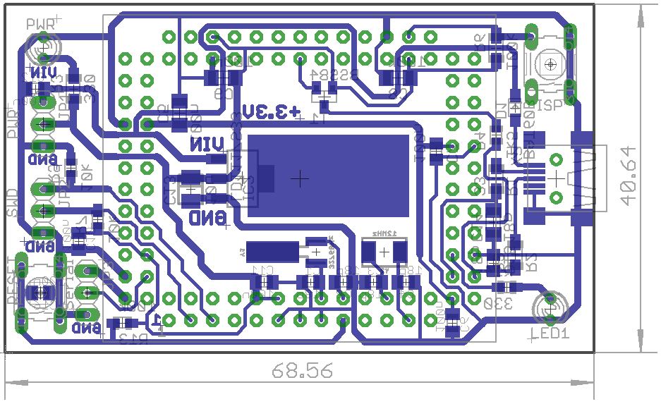
NOTE: The pictures below are just for illustration. They do not match the latest design available in the Eagle CAD project.
Printed to "Photo-paper"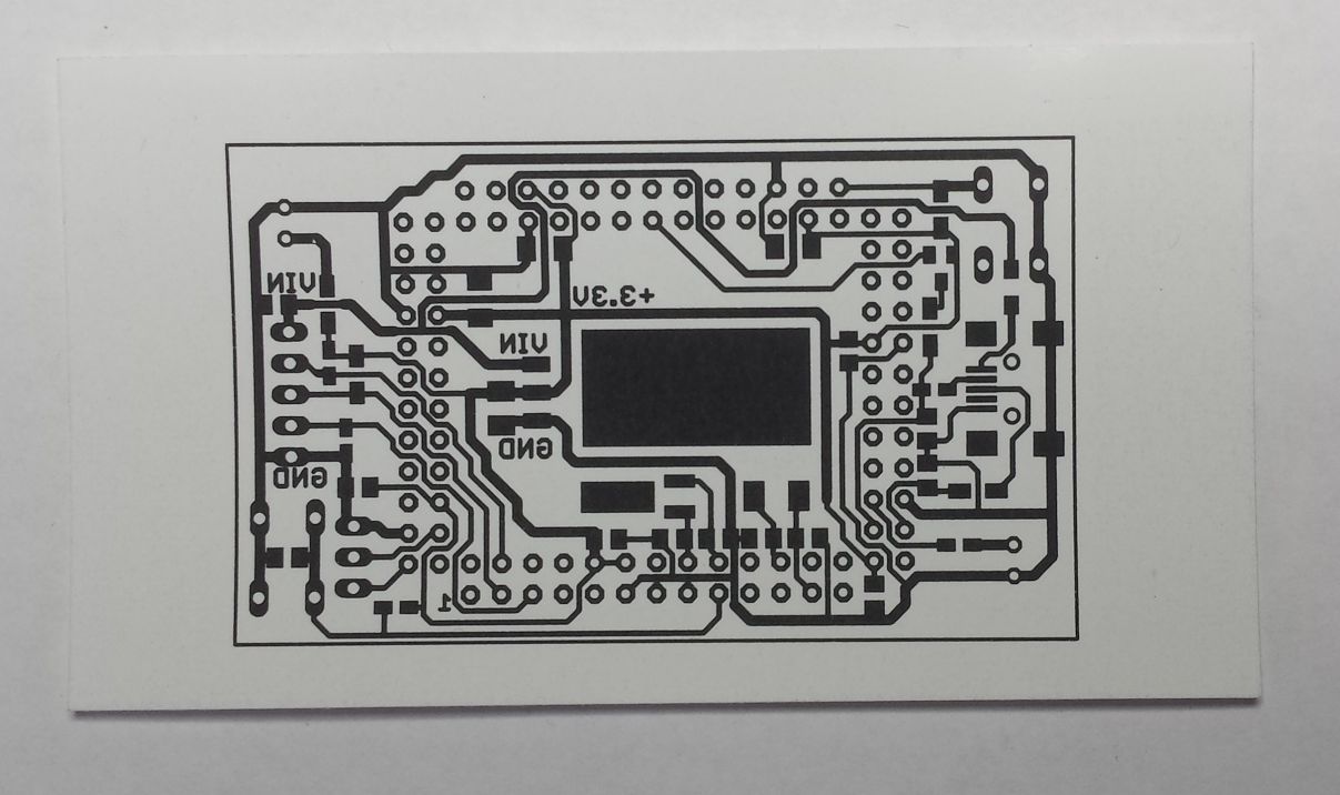
Etched.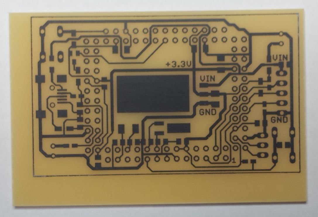
Toner removed.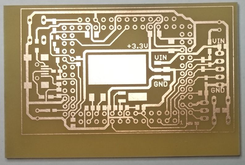
Drilling the holes...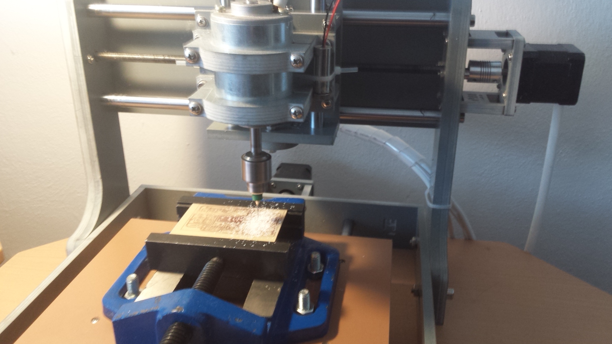
- Check the base board carefully with an ohm meter for shortcuts or cracked paths.
- In next step populate the base board with parts using tweezers and soldering iron.
- Connect a 5V power supply to the VIN and GND pins and check the voltage on the +3.3V bus. Then disconnect the power.
- Finally, place the "TQFP100 to DIP" breakout board on top of the base board and use the pins on the pinhead connectors to cross-connect the boards.
Board completed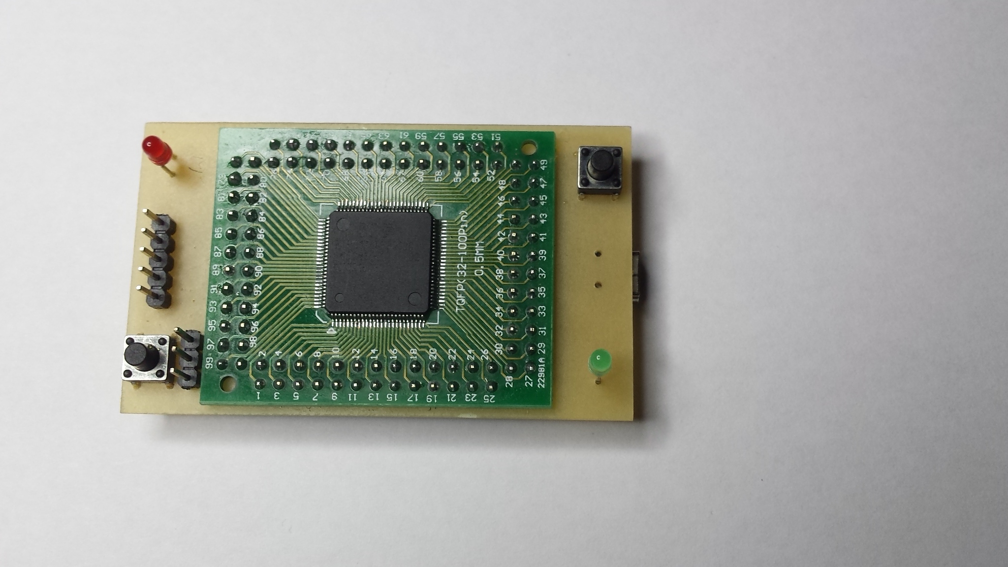
Board pinout
See Christian Lerche's pinout table or Nenad Milosevic's pinout drawing.
Programming
There are two ways how to program the board.
Serial interface, ISP and Flash Magic
- Download and install the Flash Magic utility to your PC.
- Connect an FTDI or similar "Serial to USB" converter to the board's Serial connector and over a USB cable to your PC.
- Run "Flash Magic" and set up the COM Port and Baud Rate according to the "Serial to USB converter" you are using. Set the Interface to None (ISP).
- Select the Hex File you would like to download to the chip.
NOTE: Create the.hexfile from the.binfile using thearm-none-eabi-objcopyconverter utility available in the GNU ARM Embedded Toolchain. Use the following command:arm-none-eabi-objcopy -i binary -o ihex program_name.bin program_name.hex
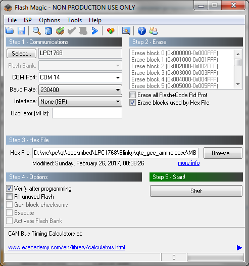
- Connect power supply to the board.
- Press and keep down the ISP button on the board.
- While the ISP button is down, push and release the Reset button.
- Release the ISP button. Consequently, the LPC1768 chip enters ISP mode and it's ready for programming.
- In Flash Magic, click on the Start button to begin downloading the program to the LPC1768 chip.
- Once the program has been downloaded to the FLASH push and release the Reset button.
SWD interface, J-Link and J-Flash
- Connect power supply to the board.
- Connect your J-Link device to the SWD connector on the board and run J-Flash.
- In File->Open project... select the default LPC1768.jflash project file.
- In Options->Project settings ->Target Interface set SWD speed after init to Auto.
- In Options->Project settings ->CPU set Clock speed to Auto detection.
- In File->Open data file... select the .bin file you would like to download to the FLASH.
- Set Start address to 0 when asked.
- In Target menu select Program & Verify (F6) to initiate download.
- Once the binary has been downloaded to the FLASH, in Target menu select Start application (F9).
Ethernet interface
See "Using LAN8720 or DP83848 modules as Ethernet interface for custom LPC1768 mbed boards".
5 comments on Home made mbed board with LPC1768 microcontroller:
Please log in to post comments.

Nice work!
Thanks for share it.