mbed API for Raspberry Pi boards.
mbedPi
This is an attempt to implement a limited number of mbed APIs for Raspberry Pi single-board computers. The project was inspired by and based on the arduPi library developed for the Arduino by Cooking Hacks .
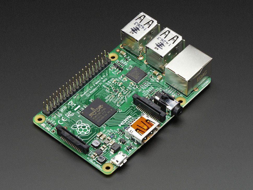
Specifications
- Chip: Broadcom BCM2836 SoC
- Core architecture: Quad-core ARM Cortex-A7
- CPU frequency: 900 MHz
- GPU: Dual Core VideoCore IV® Multimedia Co-Processor
- Memory: 1GB LPDDR2
- Operating System: Boots from Micro SD card, running a version of the Linux operating system
- Power: Micro USB socket 5V, 2A
Connectors
- Ethernet: 10/100 BaseT Ethernet socket
- Video Output: HDMI (rev 1.3 & 1.4)
- Audio Output: 3.5mm jack, HDMI
- USB: 4 x USB 2.0 Connector
- GPIO Connector: 40-pin 2.54 mm (100 mil) expansion header: 2x20 strip providing 27 GPIO pins as well as +3.3 V, +5 V and GND supply lines
- Camera Connector: 15-pin MIPI Camera Serial Interface (CSI-2)
- JTAG: Not populated
- Display Connector: Display Serial Interface (DSI) 15 way flat flex cable connector with two data lanes and a clock lane
- Memory Card Slot: Micro SDIO
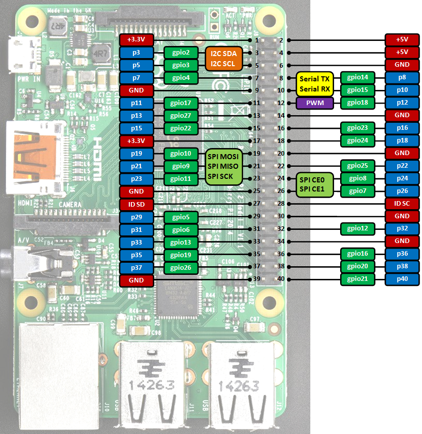
GPIO connector pinout
Information
Only the labels printed in blue/white or green/white (i.e. p3, gpio2 ...) must be used in your code. The other labels are given as information (alternate-functions, power pins, ...).
Building programs for the Raspberry Pi with mbedPi
I use Qt Creator for development, however you can use any other IDE available on the Raspberry Pi (e.g. Geany) if you like. For a quick try:
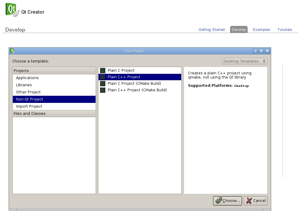
- Install Qt and the Qt Creator onto your Raspberry Pi. Then create a new "Blinky" Plain non-Qt C++ Project as follows:
- Change the main code as below:
main.cpp
#include "mbedPi.h"

int main()
{
    DigitalOut  myled(p7);

    while(1) {
        myled = 1; // LED is ON
        wait(0.2); // 200 ms
        myled = 0; // LED is OFF
        wait(1.0); // 1 sec
        printf("Blink\r\n");
    }
}
- Copy the mbedPi.zip file into your project's folder and unzip.
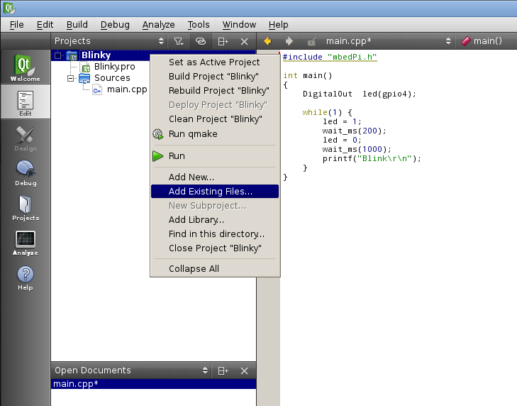
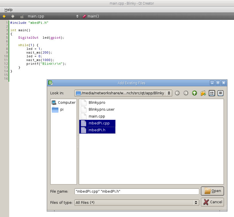
- Add the mbedPi.h and mbedPi.cpp files to your project by right clicking on the "Blinky" project and then clicking on the "Add Existing Files..." option in the local menu:
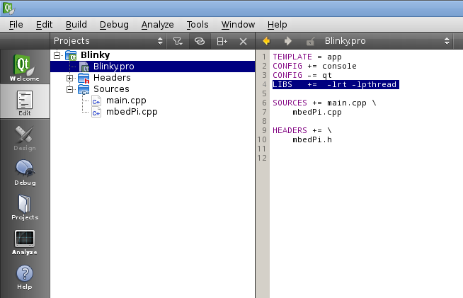
- Double click on Blinky.pro to open it for editing and add new libraries by inserting a new line as follows:
- Compile the project.
- Connect an LED through a 1k resistor to pin 7 and the ground on the Raspberry Pi GPIO connector.
- Run the binary as sudo (sudo ./Blinky) and you should see the LED blinking.

- Press Ctrl+c to stop running the application.
include/BCM2835.h
- Committer:
- hudakz
- Date:
- 18 months ago
- Revision:
- 2:131555dc6fb7
- Parent:
- 1:1f2d9982fa8c
File content as of revision 2:131555dc6fb7:
/* bcm2835.h

    C and C++ support for Broadcom BCM 2835 as used in Raspberry Pi

    Author: Mike McCauley
    Copyright (C) 2011-2013 Mike McCauley
    $Id: bcm2835.h,v 1.26 2020/01/11 05:07:13 mikem Exp mikem $
 */

#ifndef _BCM2835_H_
#define _BCM2835_H_

/*$off*/
#include <errno.h>
#include <fcntl.h>
#include <netinet/in.h>
#include <signal.h>
#include <stdlib.h>
#include <stdio.h>
#include <sys/ipc.h>
#include <sys/sem.h>
#include <sys/socket.h>
#include <sys/time.h>
#include <sys/types.h>
#include <sys/wait.h>
#include <sys/mman.h>
#include <string.h>
#include <time.h>
#include <termios.h>
#include <ctype.h>
#include <sys/ioctl.h>
#include <limits.h>
#include <algorithm>
#include <limits.h>
#include <pthread.h>
#include <poll.h>
#include "PinNames.h"

#define BCM2835_PERI_BASE       0x20000000
#define BCM2835_PERI_SIZE       0x01000000

#define BCM2835_ST_BASE			0x3000
#define BCM2835_CLOCK_BASE      0x101000
#define BCM2835_GPIO_PWM        0x20C000
#define BCM2835_BSC1_BASE       0x804000
#define BCM2835_SPI0_BASE       0x204000

/* Defines for ST
   GPIO register offsets from BCM2835_ST_BASE.
   Offsets into the ST Peripheral block in bytes per 12.1 System Timer Registers
   The System Timer peripheral provides four 32-bit timer channels and a single 64-bit free running counter.
   BCM2835_ST_CLO is the System Timer Counter Lower bits register.
   The system timer free-running counter lower register is a read-only register that returns the current value
   of the lower 32-bits of the free running counter.
   BCM2835_ST_CHI is the System Timer Counter Upper bits register.
   The system timer free-running counter upper register is a read-only register that returns the current value
   of the upper 32-bits of the free running counter.
*/
#define BCM2835_ST_CS 			0x0000 /*!< System Timer Control/Status */
#define BCM2835_ST_CLO 			0x0004 /*!< System Timer Counter Lower 32 bits */
#define BCM2835_ST_CHI 			0x0008 /*!< System Timer Counter Upper 32 bits */

// Defines for I2C
// GPIO register offsets from BCM2835_BSC*_BASE.
// Offsets into the BSC Peripheral block in bytes per 3.1 BSC Register Map
#define BCM2835_BSC_C           0x0000     ///< BSC Master Control
#define BCM2835_BSC_S           0x0004     ///< BSC Master Status
#define BCM2835_BSC_DLEN        0x0008     ///< BSC Master Data Length
#define BCM2835_BSC_A           0x000c     ///< BSC Master Slave Address
#define BCM2835_BSC_FIFO        0x0010     ///< BSC Master Data FIFO
#define BCM2835_BSC_DIV         0x0014     ///< BSC Master Clock Divider
#define BCM2835_BSC_DEL         0x0018     ///< BSC Master Data Delay
#define BCM2835_BSC_CLKT        0x001c     ///< BSC Master Clock Stretch Timeout

// Register masks for BSC_C
#define BCM2835_BSC_C_I2CEN     0x00008000  ///< I2C Enable, 0 = disabled, 1 = enabled
#define BCM2835_BSC_C_INTR      0x00000400  ///< Interrupt on RX
#define BCM2835_BSC_C_INTT      0x00000200  ///< Interrupt on TX
#define BCM2835_BSC_C_INTD      0x00000100  ///< Interrupt on DONE
#define BCM2835_BSC_C_ST        0x00000080  ///< Start transfer, 1 = Start a new transfer
#define BCM2835_BSC_C_CLEAR_1   0x00000020  ///< Clear FIFO Clear
#define BCM2835_BSC_C_CLEAR_2   0x00000010  ///< Clear FIFO Clear
#define BCM2835_BSC_C_READ      0x00000001  ///<	Read transfer

// Register masks for BSC_S
#define BCM2835_BSC_S_CLKT      0x00000200  ///< Clock stretch timeout
#define BCM2835_BSC_S_ERR       0x00000100  ///< ACK error
#define BCM2835_BSC_S_RXF       0x00000080  ///< RXF FIFO full, 0 = FIFO is not full, 1 = FIFO is full
#define BCM2835_BSC_S_TXE       0x00000040  ///< TXE FIFO full, 0 = FIFO is not full, 1 = FIFO is full
#define BCM2835_BSC_S_RXD       0x00000020  ///< RXD FIFO contains data
#define BCM2835_BSC_S_TXD       0x00000010  ///< TXD FIFO can accept data
#define BCM2835_BSC_S_RXR       0x00000008  ///< RXR FIFO needs reading (full)
#define BCM2835_BSC_S_TXW       0x00000004  ///< TXW FIFO needs writing (full)
#define BCM2835_BSC_S_DONE      0x00000002  ///< Transfer DONE
#define BCM2835_BSC_S_TA        0x00000001  ///< Transfer Active
#define BCM2835_BSC_FIFO_SIZE   16          ///< BSC FIFO size
#define BCM2835_CORE_CLK_HZ     250000000   ///< 250 MHz

    /// \brief bcm2835I2CClockDivider
    /// Specifies the divider used to generate the I2C clock from the system clock.
    /// Clock divided is based on nominal base clock rate of 250MHz
typedef enum
{
    BCM2835_I2C_CLOCK_DIVIDER_2500  = 2500, ///< 2500 = 10us = 100 kHz
    BCM2835_I2C_CLOCK_DIVIDER_626   = 626,  ///< 622 = 2.504us = 399.3610 kHz
    BCM2835_I2C_CLOCK_DIVIDER_150   = 150,  ///< 150 = 60ns = 1.666 MHz (default at reset)
    BCM2835_I2C_CLOCK_DIVIDER_148   = 148,  ///< 148 = 59ns = 1.689 MHz
} bcm2835I2CClockDivider;

/// \brief bcm2835I2CReasonCodes
/// Specifies the reason codes for the bcm2835_i2c_write and bcm2835_i2c_read functions.
typedef enum
{
    BCM2835_I2C_REASON_OK           = 0x00, ///< Success
    BCM2835_I2C_REASON_ERROR_NACK   = 0x01, ///< Received a NACK
    BCM2835_I2C_REASON_ERROR_CLKT   = 0x02, ///< Received Clock Stretch Timeout
    BCM2835_I2C_REASON_ERROR_DATA   = 0x04, ///< Not all data is sent / received
} bcm2835I2CReasonCodes;

typedef enum
{
    RPI_V2_GPIO_P1_03               = 2,    ///< Version 2, Pin P1-03
    RPI_V2_GPIO_P1_05               = 3,    ///< Version 2, Pin P1-05
} RPiGPIOPin;

#define BSC0_C        *(bsc0.addr + 0x00)
#define BSC0_S        *(bsc0.addr + 0x01)
#define BSC0_DLEN     *(bsc0.addr + 0x02)
#define BSC0_A        *(bsc0.addr + 0x03)
#define BSC0_FIFO     *(bsc0.addr + 0x04)

#define BSC_C_I2CEN   (1<< 15)
#define BSC_C_INTR    (1<< 10)
#define BSC_C_INTT    (1<< 9)
#define BSC_C_INTD    (1<< 8)
#define BSC_C_ST      (1<< 7)
#define BSC_C_CLEAR   (1<< 4)
#define BSC_C_READ    1

#define START_READ    BSC_C_I2CEN|BSC_C_ST|BSC_C_CLEAR|BSC_C_READ
#define START_WRITE   BSC_C_I2CEN|BSC_C_ST

#define BSC_S_CLKT   (1<< 9)
#define BSC_S_ERR    (1<< 8)
#define BSC_S_RXF    (1<< 7)
#define BSC_S_TXE    (1<< 6)
#define BSC_S_RXD    (1<< 5)
#define BSC_S_TXD    (1<< 4)
#define BSC_S_RXR    (1<< 3)
#define BSC_S_TXW    (1<< 2)
#define BSC_S_DONE   (1<< 1)
#define BSC_S_TA     1

#define CLEAR_STATUS    BSC_S_CLKT|BSC_S_ERR|BSC_S_DONE

#define GPFSEL0     *(gpio.addr + 0)
#define GPFSEL1     *(gpio.addr + 1)
#define GPFSEL2     *(gpio.addr + 2)
#define GPFSEL3     *(gpio.addr + 3)
#define GPFSEL4     *(gpio.addr + 4)
#define GPFSEL5     *(gpio.addr + 5)
// Reserved @ word offset 6
#define GPSET0      *(gpio.addr + 7)
#define GPSET1      *(gpio.addr + 8)
// Reserved @ word offset 9
#define GPCLR0      *(gpio.addr + 10)
#define GPCLR1      *(gpio.addr + 11)
// Reserved @ word offset 12
#define GPLEV0      *(gpio.addr + 13)
#define GPLEV1      *(gpio.addr + 14)

#define PAGESIZE    4096
#define BLOCK_SIZE  4096

/// Defines for SPI
/// GPIO register offsets from BCM2835_SPI0_BASE.
/// Offsets into the SPI Peripheral block in bytes per 10.5 SPI Register Map
#define BCM2835_SPI0_CS                      0x0000 ///< SPI Master Control and Status
#define BCM2835_SPI0_FIFO                    0x0004 ///< SPI Master TX and RX FIFOs
#define BCM2835_SPI0_CLK                     0x0008 ///< SPI Master Clock Divider
#define BCM2835_SPI0_DLEN                    0x000c ///< SPI Master Data Length
#define BCM2835_SPI0_LTOH                    0x0010 ///< SPI LOSSI mode TOH
#define BCM2835_SPI0_DC                      0x0014 ///< SPI DMA DREQ Controls

// Register masks for SPI0_CS
#define BCM2835_SPI0_CS_LEN_LONG             0x02000000 ///< Enable Long data word in Lossi mode if DMA_LEN is set
#define BCM2835_SPI0_CS_DMA_LEN              0x01000000 ///< Enable DMA mode in Lossi mode
#define BCM2835_SPI0_CS_CSPOL2               0x00800000 ///< Chip Select 2 Polarity
#define BCM2835_SPI0_CS_CSPOL1               0x00400000 ///< Chip Select 1 Polarity
#define BCM2835_SPI0_CS_CSPOL0               0x00200000 ///< Chip Select 0 Polarity
#define BCM2835_SPI0_CS_RXF                  0x00100000 ///< RXF - RX FIFO Full
#define BCM2835_SPI0_CS_RXR                  0x00080000 ///< RXR RX FIFO needs Reading ( full)
#define BCM2835_SPI0_CS_TXD                  0x00040000 ///< TXD TX FIFO can accept Data
#define BCM2835_SPI0_CS_RXD                  0x00020000 ///< RXD RX FIFO contains Data
#define BCM2835_SPI0_CS_DONE                 0x00010000 ///< Done transfer Done
#define BCM2835_SPI0_CS_TE_EN                0x00008000 ///< Unused
#define BCM2835_SPI0_CS_LMONO                0x00004000 ///< Unused
#define BCM2835_SPI0_CS_LEN                  0x00002000 ///< LEN LoSSI enable
#define BCM2835_SPI0_CS_REN                  0x00001000 ///< REN Read Enable
#define BCM2835_SPI0_CS_ADCS                 0x00000800 ///< ADCS Automatically Deassert Chip Select
#define BCM2835_SPI0_CS_INTR                 0x00000400 ///< INTR Interrupt on RXR
#define BCM2835_SPI0_CS_INTD                 0x00000200 ///< INTD Interrupt on Done
#define BCM2835_SPI0_CS_DMAEN                0x00000100 ///< DMAEN DMA Enable
#define BCM2835_SPI0_CS_TA                   0x00000080 ///< Transfer Active
#define BCM2835_SPI0_CS_CSPOL                0x00000040 ///< Chip Select Polarity
#define BCM2835_SPI0_CS_CLEAR                0x00000030 ///< Clear FIFO Clear RX and TX
#define BCM2835_SPI0_CS_CLEAR_RX             0x00000020 ///< Clear FIFO Clear RX
#define BCM2835_SPI0_CS_CLEAR_TX             0x00000010 ///< Clear FIFO Clear TX
#define BCM2835_SPI0_CS_CPOL                 0x00000008 ///< Clock Polarity
#define BCM2835_SPI0_CS_CPHA                 0x00000004 ///< Clock Phase
#define BCM2835_SPI0_CS_CS                   0x00000003 ///< Chip Select

#define BCM2835_GPFSEL0                      0x0000 ///< GPIO Function Select 0

#define BCM2835_GPEDS0                       0x0040 ///< GPIO Pin Event Detect Status 0
#define BCM2835_GPREN0                       0x004c ///< GPIO Pin Rising Edge Detect Enable 0
#define BCM2835_GPFEN0                       0x0048 ///< GPIO Pin Falling Edge Detect Enable 0
#define BCM2835_GPHEN0                       0x0064 ///< GPIO Pin High Detect Enable 0
#define BCM2835_GPLEN0                       0x0070 ///< GPIO Pin Low Detect Enable 0

/* Defines for PWM, word offsets (ie 4 byte multiples) */
#define BCM2835_PWM_CONTROL 0
#define BCM2835_PWM_STATUS  1
#define BCM2835_PWM_DMAC    2
#define BCM2835_PWM0_RANGE  4
#define BCM2835_PWM0_DATA   5
#define BCM2835_PWM_FIF1    6
#define BCM2835_PWM1_RANGE  8
#define BCM2835_PWM1_DATA   9

/* Defines for PWM Clock, word offsets (ie 4 byte multiples) */
#define BCM2835_PWMCLK_CNTL     40
#define BCM2835_PWMCLK_DIV      41
#define BCM2835_PWM_PASSWRD     (0x5A << 24)  /*!< Password to enable setting PWM clock */

#define BCM2835_PWM1_MS_MODE    0x8000  /*!< Run in Mark/Space mode */
#define BCM2835_PWM1_USEFIFO    0x2000  /*!< Data from FIFO */
#define BCM2835_PWM1_REVPOLAR   0x1000  /*!< Reverse polarity */
#define BCM2835_PWM1_OFFSTATE   0x0800  /*!< Ouput Off state */
#define BCM2835_PWM1_REPEATFF   0x0400  /*!< Repeat last value if FIFO empty */
#define BCM2835_PWM1_SERIAL     0x0200  /*!< Run in serial mode */
#define BCM2835_PWM1_ENABLE     0x0100  /*!< Channel Enable */

#define BCM2835_PWM0_MS_MODE    0x0080  /*!< Run in Mark/Space mode */
#define BCM2835_PWM_CLEAR_FIFO  0x0040  /*!< Clear FIFO */
#define BCM2835_PWM0_USEFIFO    0x0020  /*!< Data from FIFO */
#define BCM2835_PWM0_REVPOLAR   0x0010  /*!< Reverse polarity */
#define BCM2835_PWM0_OFFSTATE   0x0008  /*!< Ouput Off state */
#define BCM2835_PWM0_REPEATFF   0x0004  /*!< Repeat last value if FIFO empty */
#define BCM2835_PWM0_SERIAL     0x0002  /*!< Run in serial mode */
#define BCM2835_PWM0_ENABLE     0x0001  /*!< Channel Enable */

#define PWM_CHANNEL             0

/// \brief bcm2835SPIBitOrder
/// Specifies the SPI data bit ordering
typedef enum
{
    LSBFIRST = 0,  ///< LSB First
    MSBFIRST = 1///< MSB First
} bcm2835SPIBitOrder;

/// \brief bcm2835SPIMode
/// Specify the SPI data mode
typedef enum
{
    SPI_MODE0 = 0,  ///< CPOL = 0, CPHA = 0
    SPI_MODE1 = 1,  ///< CPOL = 0, CPHA = 1
    SPI_MODE2 = 2,  ///< CPOL = 1, CPHA = 0
    SPI_MODE3 = 3,  ///< CPOL = 1, CPHA = 1
} bcm2835SPIMode;

/// \brief bcm2835SPIChipSelect
/// Specify the SPI chip select pin(s)
typedef enum
{
    SPI_CS0 = 0,     ///< Chip Select 0
    SPI_CS1 = 1,     ///< Chip Select 1
    SPI_CS2 = 2,     ///< Chip Select 2 (ie pins CS1 and CS2 are asserted)
    SPI_CS_NONE = 3, ///< No CS, control it yourself
} bcm2835SPIChipSelect;

/// \brief bcm2835SPIClockDivider
/// Specifies the divider used to generate the SPI clock from the system clock.
/// Figures below give the divider, clock period and clock frequency.
typedef enum
{
    SPI_CLOCK_DIV65536 = 0,       ///< 65536 = 256us = 4kHz
    SPI_CLOCK_DIV32768 = 32768,   ///< 32768 = 126us = 8kHz
    SPI_CLOCK_DIV16384 = 16384,   ///< 16384 = 64us = 15.625kHz
    SPI_CLOCK_DIV8192  = 8192,    ///< 8192 = 32us = 31.25kHz
    SPI_CLOCK_DIV4096  = 4096,    ///< 4096 = 16us = 62.5kHz
    SPI_CLOCK_DIV2048  = 2048,    ///< 2048 = 8us = 125kHz
    SPI_CLOCK_DIV1024  = 1024,    ///< 1024 = 4us = 250kHz
    SPI_CLOCK_DIV512   = 512,     ///< 512 = 2us = 500kHz
    SPI_CLOCK_DIV256   = 256,     ///< 256 = 1us = 1MHz
    SPI_CLOCK_DIV128   = 128,     ///< 128 = 500ns = = 2MHz
    SPI_CLOCK_DIV64    = 64,      ///< 64 = 250ns = 4MHz
    SPI_CLOCK_DIV32    = 32,      ///< 32 = 125ns = 8MHz
    SPI_CLOCK_DIV16    = 16,      ///< 16 = 50ns = 20MHz
    SPI_CLOCK_DIV8     = 8,       ///< 8 = 25ns = 40MHz
    SPI_CLOCK_DIV4     = 4,       ///< 4 = 12.5ns 80MHz
    SPI_CLOCK_DIV2     = 2,       ///< 2 = 6.25ns = 160MHz
    SPI_CLOCK_DIV1     = 1,       ///< 0 = 256us = 4kHz
} bcm2835SPIClockDivider;

/*! \brief bcm2835PWMClockDivider
  Specifies the divider used to generate the PWM clock from the system clock.
  Figures below give the divider, clock period and clock frequency.
  Clock divided is based on nominal PWM base clock rate of 19.2MHz
  The frequencies shown for each divider have been confirmed by measurement
*/
typedef enum
{
    BCM2835_PWM_CLOCK_DIVIDER_4096  = 4096,    /*!< 4096 = 4.6875kHz */
    BCM2835_PWM_CLOCK_DIVIDER_2048  = 2048,    /*!< 2048 = 9.375kHz */
    BCM2835_PWM_CLOCK_DIVIDER_1024  = 1024,    /*!< 1024 = 18.75kHz */
    BCM2835_PWM_CLOCK_DIVIDER_512   = 512,     /*!< 512 = 37.5kHz */
    BCM2835_PWM_CLOCK_DIVIDER_256   = 256,     /*!< 256 = 75kHz */
    BCM2835_PWM_CLOCK_DIVIDER_128   = 128,     /*!< 128 = 150kHz */
    BCM2835_PWM_CLOCK_DIVIDER_64    = 64,      /*!< 64 = 300kHz */
    BCM2835_PWM_CLOCK_DIVIDER_32    = 32,      /*!< 32 = 600.0kHz */
    BCM2835_PWM_CLOCK_DIVIDER_16    = 16,      /*!< 16 = 1.2MHz */
    BCM2835_PWM_CLOCK_DIVIDER_8     = 8,       /*!< 8 = 2.4MHz */
    BCM2835_PWM_CLOCK_DIVIDER_4     = 4,       /*!< 4 = 4.8MHz */
    BCM2835_PWM_CLOCK_DIVIDER_2     = 2,       /*!< 2 = 9.6MHz, fastest you can get */
    BCM2835_PWM_CLOCK_DIVIDER_1     = 1        /*!< 1 = 4.6875kHz, same as divider 4096 */
} bcm2835PWMClockDivider;

/*! \brief bcm2835PWMClockDivider
  Specifies the divider used to generate the PWM clock from the system clock.
  Figures below give the divider, clock period and clock frequency.
  Clock divided is based on nominal PWM base clock rate of 19.2MHz
  The frequencies shown for each divider have been confirmed by measurement
*/
typedef enum
{
    BCM2835_PWM_PERIOD_212_US  = 4096,    /*!< 213.33 us  = 4.6875kHz */
    BCM2835_PWM_PERIOD_107_US  = 2048,    /*!< 106.66 us  = 9.375kHz  */
    BCM2835_PWM_PERIOD_53_US   = 1024,    /*!<  53.33 us  = 18.75kHz  */
    BCM2835_PWM_PERIOD_27_US   =  512,    /*!<  26.66 us  = 37.5kHz   */
    BCM2835_PWM_PERIOD_13_US   =  256,    /*!<  13.33 us  = 75kHz     */
    BCM2835_PWM_PERIOD_6_6_US  =  128,    /*!<   6.66 us  = 150kHz    */
    BCM2835_PWM_PERIOD_3_3_US  =   64,    /*!<   3.33 us  = 300kHz    */
    BCM2835_PWM_PERIOD_1_7_US  =   32,    /*!<   1.66 us  = 600.0kHz  */
    BCM2835_PWM_PERIOD_833_NS  =   16,    /*!< 833.33 ns  = 1.2MHz    */
    BCM2835_PWM_PERIOD_417_NS  =    8,    /*!< 416.66 ns  = 2.4MHz    */
    BCM2835_PWM_PERIOD_208_NS  =    4,    /*!< 208.33 ns  = 4.8MHz    */
    BCM2835_PWM_PERIOD_104_NS  =    2,    /*!< 104.16 ns  = 9.6MHz,   */
} bcm2835_PWM_PulsePeriod;

typedef enum
{
    BCM2835_GPIO_FSEL_INPT  = 0b000,   ///< Input
    BCM2835_GPIO_FSEL_OUTP  = 0b001,   ///< Output
    BCM2835_GPIO_FSEL_ALT0  = 0b100,   ///< Alternate function 0
    BCM2835_GPIO_FSEL_ALT1  = 0b101,   ///< Alternate function 1
    BCM2835_GPIO_FSEL_ALT2  = 0b110,   ///< Alternate function 2
    BCM2835_GPIO_FSEL_ALT3  = 0b111,   ///< Alternate function 3
    BCM2835_GPIO_FSEL_ALT4  = 0b011,   ///< Alternate function 4
    BCM2835_GPIO_FSEL_ALT5  = 0b010,   ///< Alternate function 5
    BCM2835_GPIO_FSEL_MASK  = 0b111    ///< Function select bits mask
} bcm2835FunctionSelect;

namespace unistd {
    //All functions of unistd.h must be called like this: unistd::the_function()
    #include <unistd.h>
}

enum Representation{
    BIN,
    OCT,
    DEC,
    HEX,
    BYTE
};

typedef enum {
    LOW     = 0,
    HIGH    = 1,
    RISING  = 2,
    FALLING = 3,
    BOTH    = 4
} Digivalue;
//
/*$on*/
//
typedef bool boolean;
typedef unsigned char   byte;

struct bcm2835_peripheral
{
    unsigned long           addr_p;
    int                     mem_fd;
    void*                   map;
    volatile unsigned int*  addr;
};


/* Helper functions */
int         getBoardRev();
uint32_t*   mapmem(const char* msg, size_t size, int fd, off_t off);
void        setBoardRev(int rev);
pthread_t*  getThreadIdFromPin(int pin);
void*       threadFunction(void* args);
uint32_t    bcm2835_peri_read(volatile uint32_t* paddr);
uint32_t    bcm2835_peri_read_nb(volatile uint32_t* paddr);
void        bcm2835_peri_write(volatile uint32_t* paddr, uint32_t value);
void        bcm2835_peri_write_nb(volatile uint32_t* paddr, uint32_t value);
void        bcm2835_peri_set_bits(volatile uint32_t* paddr, uint32_t value, uint32_t mask);
void        bcm2835_gpio_fsel(uint8_t pin, uint8_t mode);
uint64_t    bcm2835_systimer_read(void);
void        bcm2835_delay (unsigned int millis);
void        bcm2835_pwm_set_clock(uint32_t divisor);
void        bcm2835_pwm_set_mode(uint8_t channel, uint8_t markspace, uint8_t enabled);
void        bcm2835_pwm_set_range(uint8_t channel, uint32_t range);
void        bcm2835_pwm_set_data(uint8_t channel, uint32_t data);
void        gpio_dir(PinName pin, PinDirection direction);
void        gpio_mode(PinName pin, PinMode mode);
void        gpio_write(PinName pin, int value);
int         gpio_read(PinName pin);
uint8_t     shiftIn(PinName dPin, PinName cPin, bcm2835SPIBitOrder order);
void        shiftOut(PinName dPin, PinName cPin, bcm2835SPIBitOrder order, uint8_t val);
void        attachInterrupt(PinName p, void (*f) (), Digivalue m);
void        detachInterrupt(PinName p);

typedef void (*FunctionPointer) ();

static int REV = 0;

#endif	// _BCM2835_H_
