mbed API for Raspberry Pi boards.
mbedPi
This is an attempt to implement a limited number of mbed APIs for Raspberry Pi single-board computers. The project was inspired by and based on the arduPi library developed for the Arduino by Cooking Hacks .
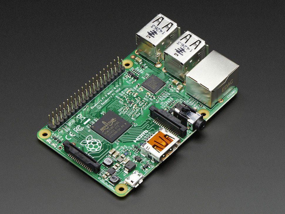
Specifications
- Chip: Broadcom BCM2836 SoC
- Core architecture: Quad-core ARM Cortex-A7
- CPU frequency: 900 MHz
- GPU: Dual Core VideoCore IV® Multimedia Co-Processor
- Memory: 1GB LPDDR2
- Operating System: Boots from Micro SD card, running a version of the Linux operating system
- Power: Micro USB socket 5V, 2A
Connectors
- Ethernet: 10/100 BaseT Ethernet socket
- Video Output: HDMI (rev 1.3 & 1.4)
- Audio Output: 3.5mm jack, HDMI
- USB: 4 x USB 2.0 Connector
- GPIO Connector: 40-pin 2.54 mm (100 mil) expansion header: 2x20 strip providing 27 GPIO pins as well as +3.3 V, +5 V and GND supply lines
- Camera Connector: 15-pin MIPI Camera Serial Interface (CSI-2)
- JTAG: Not populated
- Display Connector: Display Serial Interface (DSI) 15 way flat flex cable connector with two data lanes and a clock lane
- Memory Card Slot: Micro SDIO
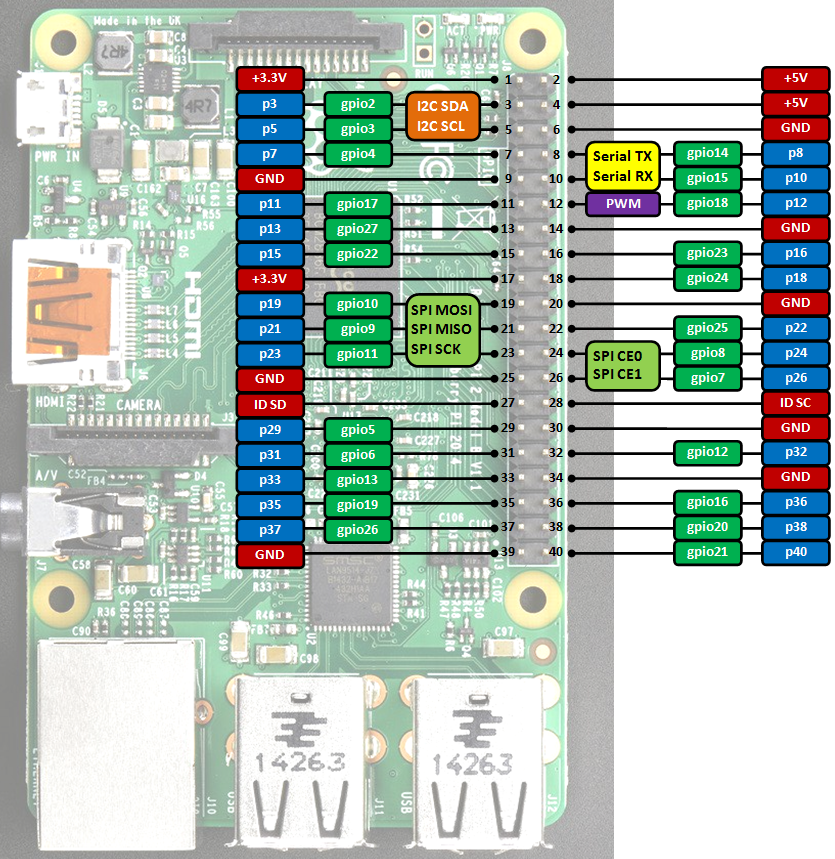
GPIO connector pinout
Information
Only the labels printed in blue/white or green/white (i.e. p3, gpio2 ...) must be used in your code. The other labels are given as information (alternate-functions, power pins, ...).
Building programs for the Raspberry Pi with mbedPi
I use Qt Creator for development, however you can use any other IDE available on the Raspberry Pi (e.g. Geany) if you like. For a quick try:
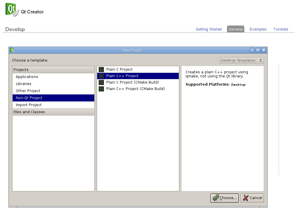
- Install Qt and the Qt Creator onto your Raspberry Pi. Then create a new "Blinky" Plain non-Qt C++ Project as follows:
- Change the main code as below:
main.cpp
#include "mbedPi.h"

int main()
{
    DigitalOut  myled(p7);

    while(1) {
        myled = 1; // LED is ON
        wait(0.2); // 200 ms
        myled = 0; // LED is OFF
        wait(1.0); // 1 sec
        printf("Blink\r\n");
    }
}
- Copy the mbedPi.zip file into your project's folder and unzip.
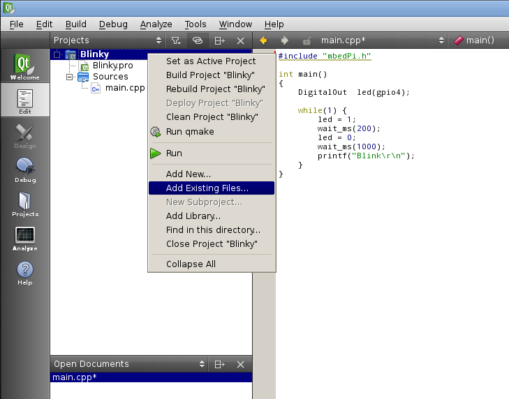
- Add the mbedPi.h and mbedPi.cpp files to your project by right clicking on the "Blinky" project and then clicking on the "Add Existing Files..." option in the local menu:
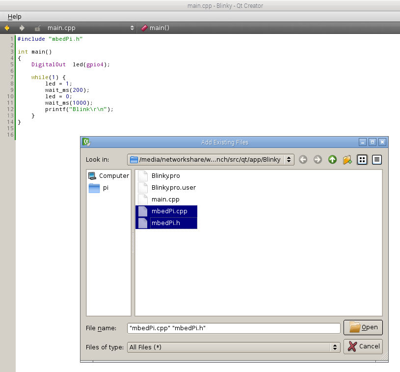
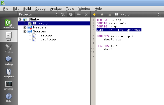
- Double click on Blinky.pro to open it for editing and add new libraries by inserting a new line as follows:
- Compile the project.
- Connect an LED through a 1k resistor to pin 7 and the ground on the Raspberry Pi GPIO connector.
- Run the binary as sudo (sudo ./Blinky) and you should see the LED blinking.

- Press Ctrl+c to stop running the application.
Diff: include/PinNames.h
- Revision:
- 1:1f2d9982fa8c
--- /dev/null	Thu Jan 01 00:00:00 1970 +0000
+++ b/include/PinNames.h	Tue Dec 20 12:08:07 2022 +0000
@@ -0,0 +1,111 @@
+#ifndef _PIN_NAMES_H_
+#define _PIN_NAMES_H_
+
+typedef enum {
+    // Not connected
+    NC = (int)0xFFFFFFFF,
+
+    // GPIO names
+    gpio2       = 2,
+    gpio3       = 3,
+    gpio4       = 4,
+    gpio5       = 5,
+    gpio6       = 6,
+    gpio7       = 7,
+    gpio8       = 8,
+    gpio9       = 9,
+    gpio10      = 10,
+    gpio11      = 11,
+    gpio12      = 12,
+    gpio13      = 13,
+    gpio14      = 14,
+    gpio15      = 15,
+    gpio16      = 16,
+    gpio17      = 17,
+    gpio18      = 18,
+    gpio19      = 19,
+    gpio20      = 20,
+    gpio21      = 21,
+    gpio22      = 22,
+    gpio23      = 23,
+    gpio24      = 24,
+    gpio25      = 25,
+    gpio26      = 26,
+    gpio27      = 27,
+
+    // Rapsberry Pi pin names
+    p3          = gpio2,
+    p5          = gpio3,
+    p7          = gpio4,
+    p8          = gpio14,
+    p10         = gpio15,
+    p11         = gpio17,
+    p12         = gpio18,
+    p13         = gpio27,
+    p15         = gpio22,
+    p16         = gpio23,
+    p18         = gpio24,
+    p19         = gpio10,
+    p21         = gpio9,
+    p22         = gpio25,
+    p23         = gpio11,
+    p24         = gpio8,
+    p26         = gpio7,
+    p29         = gpio5,
+    p31         = gpio6,
+    p32         = gpio12,
+    p33         = gpio13,
+    p35         = gpio19,
+    p36         = gpio16,
+    p37         = gpio26,
+    p38         = gpio20,
+    p40         = gpio21,
+
+    // Extension board V2.1 pin names
+    P0          = gpio17,
+    P1          = gpio18,
+    P2          = gpio27,
+    P3          = gpio22,
+    P4          = gpio23,
+    P5          = gpio24,
+    P6          = gpio25,
+    P7          = gpio4,
+    CE1         = gpio7,
+    CE0         = gpio8,
+    CS          = gpio8,
+    SCLK        = gpio11,
+    MISO        = gpio9,
+    MOSI        = gpio10,
+    RXD         = gpio15,
+    TXD         = gpio14,
+    SCL         = gpio3,
+    SDA         = gpio2,
+    PWM         = gpio18,
+
+    // Arduino pin names on the Extension board V2.1
+    D2          = gpio18,
+    D3          = gpio23,
+    D4          = gpio24,
+    D5          = gpio25,
+    D6          = gpio4,
+    D7          = gpio17,
+    D8          = gpio27,
+    D9          = gpio22
+} PinName;
+
+typedef enum
+{
+    PIN_INPUT,
+    PIN_OUTPUT
+} PinDirection;
+
+typedef enum
+{
+    PullNone,
+    PullUp,
+    PullDown,
+    OpenDrain,
+    PullDefault = PullNone
+} PinMode;
+
+#endif	// _PIN_NAMES_H_
