Barcode reader with a TCD1304AP TOSHIBA CCD linear image sensor and NUCLEO-F103RB board.
Barcode Reader
Barcodes represent data by varying the widths of spaces and bars. These barcodes, now commonly referred to as linear or one-dimensional (1D), can be scanned by barcode readers. In this project a TCD1304AP TOSHIBA CCD linear image sensor is used to scan barcodes. The obtained light intensity stream is passed to the ZBar library streamlined for embedded use.
| Flow chart | 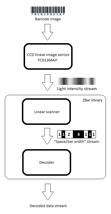 |
TCD1304AP Driver
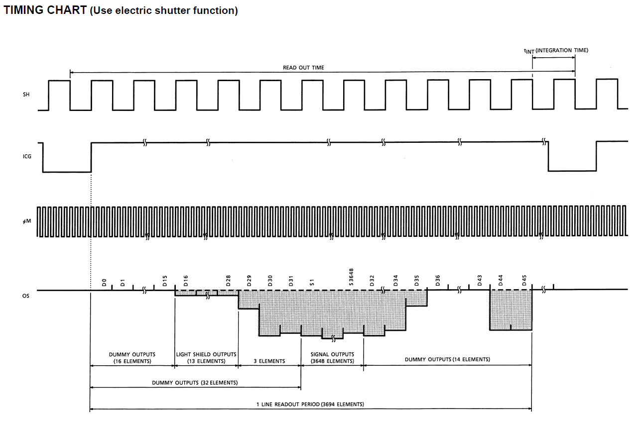
The TCD1304AP requires three clock signals (see below the Timing chart). It can operate with or without a built-in electronic shutter. In this project the electronic shutter is used to control the integration (exposure) time:
I used STM32CubeIDE to build the driver for the TCD1304AP sensor and then merged it with the Mbed OS 2 project.
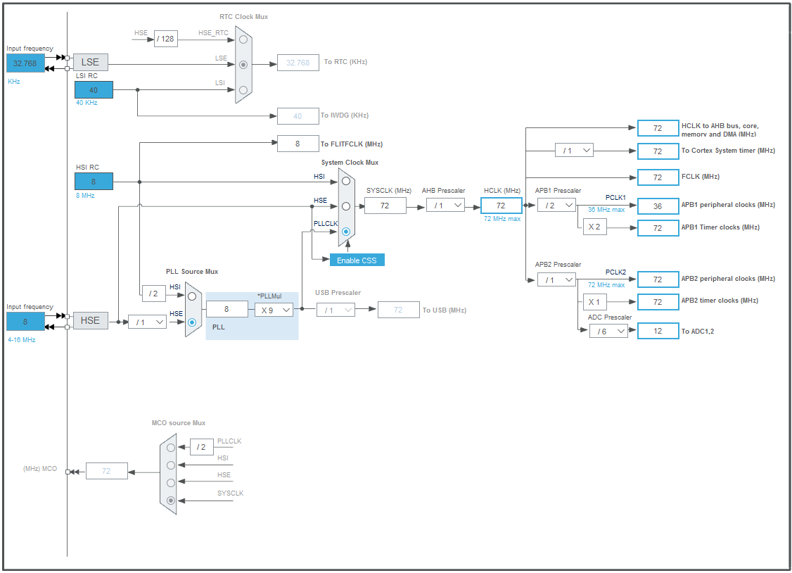
STM32F103RB clock configuration
STM32F103RB pinout
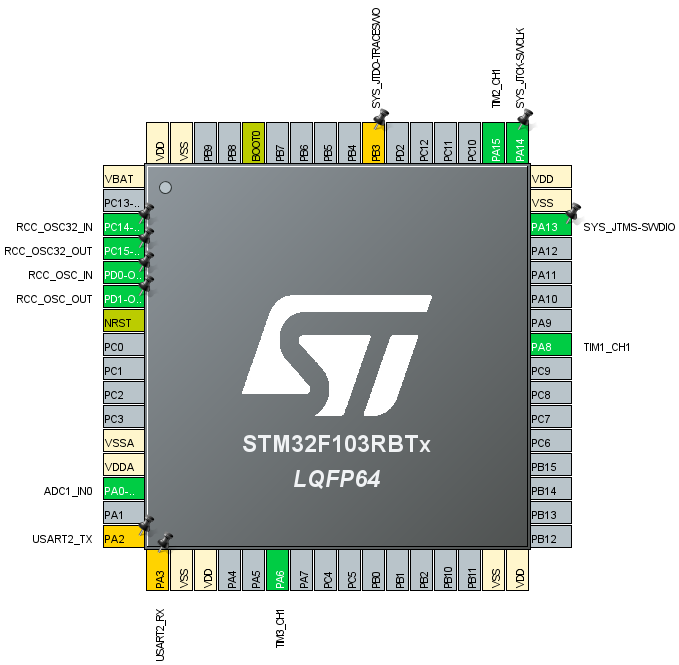
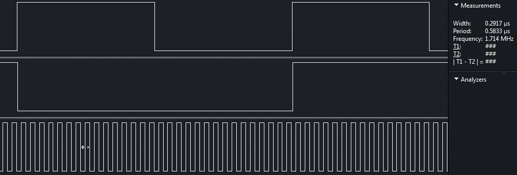
- The signal for TCD1304AP's master clock (fiM) is generated by STM32F103's TIM1 timer and it is output at pin PA_8.
- The Shift Gate clock signal (SH) is produced by timer TIM2 and it's available at pin PA_15.
- The Integration Clear Gate pulses (ICG) are generated by timer TIM3 at pin PA_6.
The TCD1304AP's master clock runs at 1.714MHz. Pixel data is available at its output (OS) after each four pulses. To keep up with such speed DMA (Direct Memmory Access) is used to move the voltage data produced by the ADC (Analog to Digital Convertor) into the STM32F103's SRAM. The ADC is clocked with a 12MHz signal and runs in continuous mode.
