Angry Balls
Overview
I created a simple game called Angry Balls for the Mbed ARM-based platform. The setup for the game features a uLCD-144-G2 screen for displaying graphics, an MPR121 capacitive touch keypad from Sparkfun for user controls, and a PCB-mountable simple speaker from Sparkfun with a 2N3904 amplifier for sound effects. The game also features the display of an image on the LCD that is loaded from an SD card.
How to Play
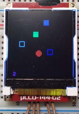
Here is a snapshot of the game being played:

Solid Green box => USER
Solid Grey box => PAYLOAD
Hollow White box => Start and reset location for PAYLOAD
Hollow Blue box => PORTAL
Solid Red ball => ANGRY BALL
The object of the game is to control the USER via the touch keypad to push the PAYLOAD into the PORTAL to score a point. Upon scoring, the PORTAL will change locations. If the ANGRY BALL, which is furiously flying around the room, comes into contact with the PAYLOAD then the game is over. The USER is impervious to the ANGRY BALL. With this in mind, the USER can deflect the ANGRY BALL away from the PORTAL. If the USER finds him/herself in a tight situation, the PAYLOAD can be pushed into the wall, at which point the PAYLOAD will respawn (from the hollow white box). Be wary you don't force the PAYLOAD to reset whilst the ANGRY BALL is making a bee-line for the reset area. The USER moves slower while pushing the PAYLOAD due to the PAYLOAD's "weight".
Note: The PORTAL is called the PORTAL because I couldn't think of a good name. It doesn't actually teleport the PAYLOAD like you think it would. In fact, the walls themselves are actually the portals in this case.
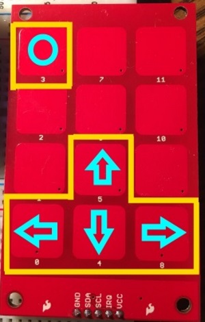
The player controls the USER with the keys on the touch pad. The 3 Key is the "Action" key, used for starting, pausing, placing the ball, etc.
Here are the touch pad key bindings:

Demo
Here is a video of the game being played (note how angry that ball is... pretty scary):
Hardware Setup
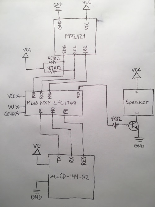
Here is a schematic of the devices used:

Here are all the pin connections to the Mbed microcontroller:
| Device Pin | Mbed Pin |
|---|---|
| LCD +5V | VU |
| LCD GND | GND |
| LCD RX | p9 |
| LCD TX | p10 |
| LCD RES | p11 |
| 2N3904 B | p21 |
| Keypad VCC | VCC |
| Keypad GND | GND |
| Keypad IRQ | p26 |
| Keypad SCL | p27 |
| Keypad SDA | p28 |
Remember
Remember to place I2C pullups on the SDA and SCL lines for the keypad. I have used 4.7K ohm resistors. Make sure they are not in-series.
Remember to supply +5V to the LCD via the VU pin on the Mbed. All other power pins will be +3.3V except this one.
Code
Here is the code for the game:
Import programangryballs
A simple game
Please log in to post comments.
