Wireless Connection Breakout Board
Team Members
Anthony Jones - Section B
Garren Boggs - Section B
David Cox - Section A
Parth Patel - Section A
Description
The purpose of this project was to simplify the usage of the Adafruit WiFi Huzzah chip and the Adafruit Bluetooth LE chip. Both chips are hooked up to the mbed with a total of three wires, one tx, one rx, and one select. A tri-state buffer was used to split up the inputs and outputs of the serial connection from the mbed to the two chips. An inverter was used to correctly place the needed value of the select line from the mbed to the tri-state buffer.
The first part of the project was to implement these features on a breadboard for testing and demonstration purposes. The second part entailed the designing of a PCB breakout board for these chips.
Needed Components
- mbed LPC1768
- Adafruit Huzzah ESP8266 Breakout
- Adafruit Bluefruit LE UART Friend
- Quadruple 3-State Buffer
- Hex Inverter
- Barrel Jack Adapter
Images

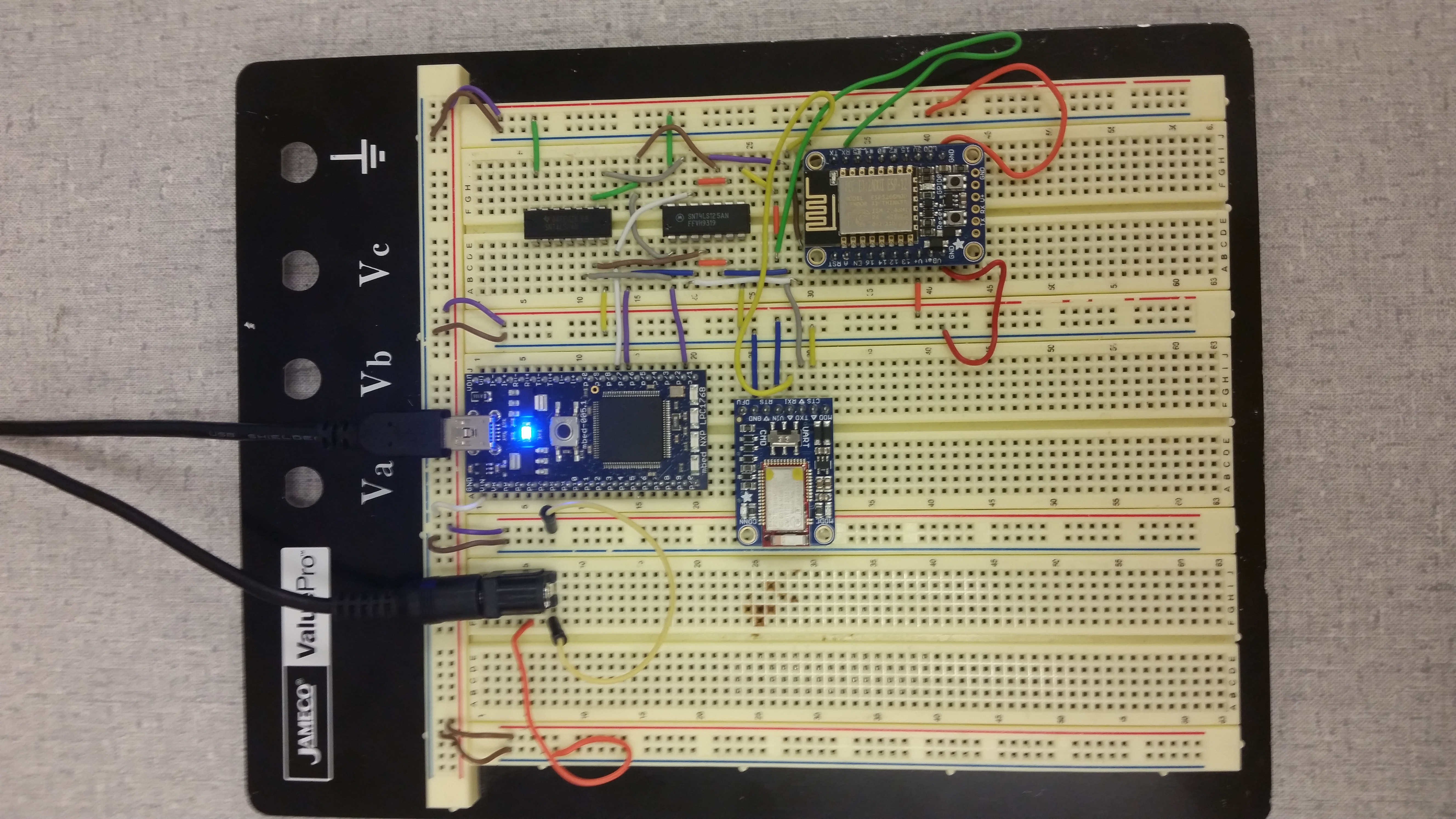
Breadboard Hookup Guide
This is a guide to how the needed components were hooked up to a breadboard for testing purposes. The PCB design detailed further below would replace this.
- Note: A barrel jack was needed to power the wifi chip as it sucks too much current.
| mbed | Tri-State Buffer |
|---|---|
| p22 | p1 - 1G |
| p22 | p10 - 3G |
| p27 | p3 - 1Y |
| p27 | p6 - 2Y |
| p28 | p9 - 3A |
| p28 | p12 - 4A |
| mbed | Inverter |
|---|---|
| p22 | p5 - 3A |
| p22 | p9 - 4A |
| Inverter | Tri-State Buffer |
|---|---|
| p6 - 3Y | p4 - 2G |
| p8 - 4Y | p13 - 4G |
| Tri-State Buffer | Huzzah ESP8266 |
|---|---|
| p2 - 1A | Tx |
| p8 - 3Y | Rx |
| Tri-State Buffer | Bluetooth LE UART |
|---|---|
| p5 - 2A | Tx |
| p11 - 4Y | Rx |
WiBt Breakout PCB Board
This is the second part of the project where the creation of a WiFi and Bluetooth (or the WiBt) breakout board is detailed.
Schematic of Pin Hookups

Description
As previously mentioned, the second part of this project included the creation of a PCB breakout board. The schematic, shown below, was created through the use of EAGLE PCB Design Software.

The ultimate purpose of this board and project is to simplify the usage of both WiFi and Bluetooth. After hooking up three pins, the tx and rx pins of a serial connection, and the select pin, to the breakout board, one would have to import the library posted further below on this page. Afterwards, including the one header file in code would potentially allow the user to access both WiFi and Bluetooth in their project.
Board Hookup to Mbed
| mbed | WiBt Breakout |
|---|---|
| N/A | Vin (+5v External) |
| GND | GND |
| p28 | Rx |
| p27 | Tx |
| p22 | SEL |
| p26 (optional) | RST |
Video
Code
Library
Library for use with the WiBt breakout board.
Import libraryWirelessInterface
ECE 4180 final project. Used to connected with both Adafruit Huzzah WiFi and Adafruit Bluetooth LE UART.
Test Program
Program used with the breadboard to test the WirelessInterface library linked above.
Import programWirelessInterface_Demo
Program to test WirelessInterface library.
Please log in to post comments.
