Wifi Controled ShadowBot
 Karl Fischer.
0
replies
Karl Fischer.
0
replies
This page describes how to use a wifi module to communicate with a modified shadowbot. Halleffect sensors are utilized to allow the robot to move in a straight line to counter manufacturing differences between motor output. The robot creates a simple webpage with a text field for input. The Input from the form is saved to an SD card and then parsed by the robot to determine which directions it should travel and for what duration. The commands are sent in a simple format the direction(f,b,r,l) then the duration (0-9), or s to play a sound. The webpage has an example default value stored for directions that can be sent to test the system. When sending custom commands always remember to end the custom direction with the word stop, the code looks for that sub string to determine the length of commands sent.This is parsed and used to command the wheels which correct for motor output during forward and backward sessions to get the robot going in a straight line.

It is important to note that the length of the direction information sent to the robot has a limit that is defined in the code so although a large number of directions may be sent it is possible to hit a breaking point. This limit can be changed easily by just increasing the buffer in the code.
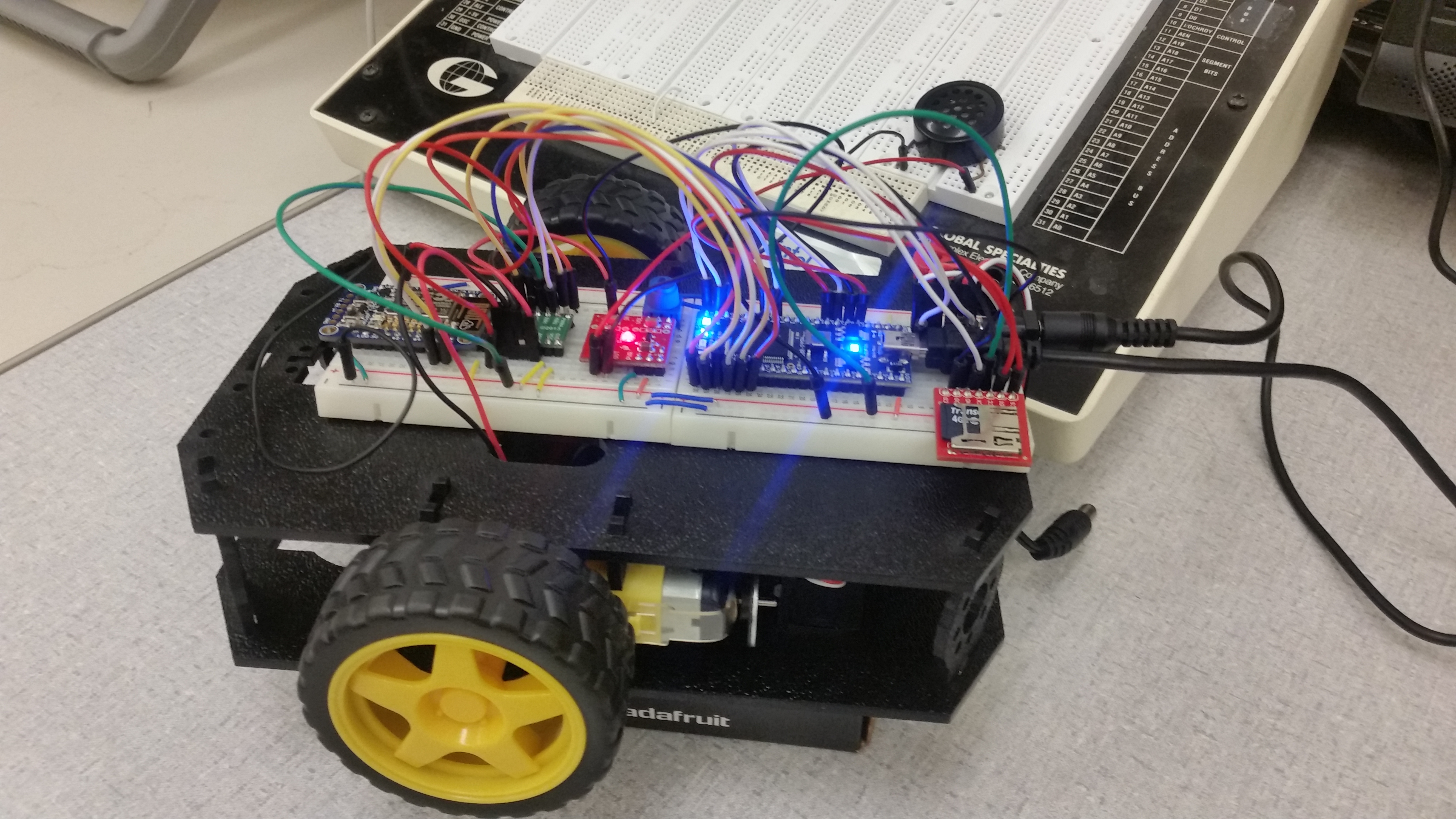
The final assembly up on some blocks
Parts List
For convinced the parts list is provided including wiring diagrams.

https://www.sparkfun.com/products/11089
https://www.sparkfun.com/products/11044
Wiring
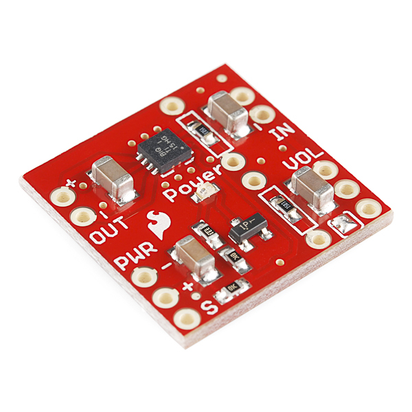
| mbed | TPA2005D1 | Speaker |
|---|---|---|
| gnd | pwr - (gnd), in - | |
| Vout (3.3V) or 5V | pwr + | |
| p18 D/A | in + | |
| out + | + | |
| out - | - | |
| Any DigitalOut px(optional) | S (low for shutdown) |

https://www.sparkfun.com/products/544
Wiring
| mbed | MicroSD Breakout |
|---|---|
| 8 | CS |
| 5 | DI |
| VOUT | VCC |
| 7 | SCK |
| GND | GND |
| 6 | D) |
| CD |

https://www.adafruit.com/product/2471
| Huzzah | mbed LPC1768 | External 5V DC supply >=500MA |
|---|---|---|
| gnd | gnd | gnd |
| TX | RX - p27 | |
| RX | TX - p28 | |
| V+ | 5VDC | |
| RST | p26 (optional) |

https://www.pololu.com/product/713
Wiring
| mbed | Dual H-bridge | Robot DC motors | Battery |
|---|---|---|---|
| Vin | Vmot | + | |
| Gnd | Gnd | - | |
| Vout | Vcc | ||
| p21 | PWMB | ||
| p22 | BIN2 | ||
| p23 | BIN1 | ||
| p24 | AIN1 | ||
| p25 | AIN2 | ||
| p26 | PWMA | ||
| Vout | /STBY | ||
| A01 | left-red | ||
| A02 | left-blk | ||
| B02 | right-blk | ||
| B01 | right-red |

https://www.sparkfun.com/products/12629
Wiring
| mbed | Encoder Left | Encoder Right |
| p19 | Data Wire | |
| p20 | Data Wire | |
| Vout | Red Wire | Red Wire |
| GND | Black Wire | Black Wire |

The shadow bot was built as per the assembly instructions included bellow the instructions also go into detail on how to integrate the wheel encoder kit into the chassis. The breadboard used is stuck to the top back of the chassis the second breadboard is only attached to the first breadboard to allow the chassis to be used again in the future for different design projects.
https://learn.sparkfun.com/tutorials/assembly-guide-for-redbot-with-shadow-chassis/all

Code
All of the code developed was modified from various projects that implemented integration of individual components into the mbed.
Import programWiFI_Robot
Simple code to control a robot by sending it a string of commands over wifi
Last commit 02 Nov 2016 by Karl Fischer
Please log in to post comments.