MAX7456 Video Overlay
Introduction
This project is about printing different pieces of text onto a tv screen using the mbed and the MAX7455 module. This is done by using the SPI, where the mbed will act as the master and send signals to the MAX7455 module (the slave). The MAX7455 will be connected to an AV-cable which is then inserted into a TV.
MAX7455
This module is described as a Single-channel Monochrome On-Screen Display with Integrated EEPROM. The following pin designations are:
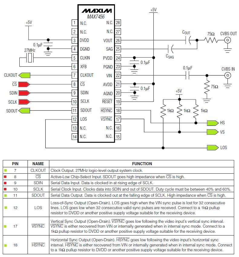
The pins that are highlighted in red(input) and green(output) will be the ones that I will be using on the bread board.
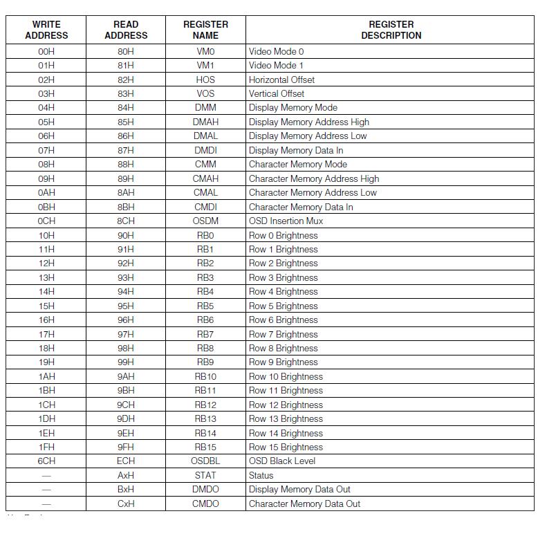
The MAX7556 contains a number of registers, which are all used for different purposes, to write data to one of the registers it must be sent in a 16-bit command to the write address. All registers have separate write addresses and read addresses. The 16-bit command represents the data and the address where the first half is the address (8-bit) and the second half is the data (8-bit).
Here is the list of registers:
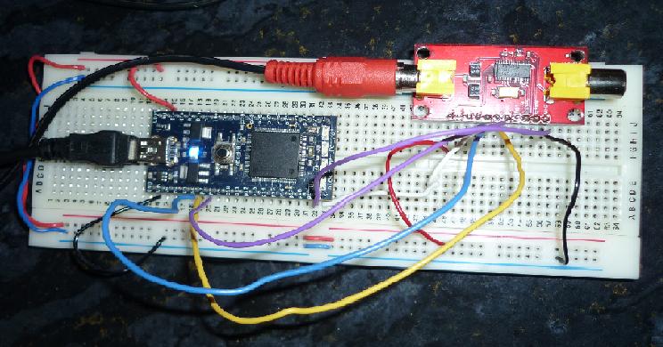
After reading through the data sheet, I decided to set up the circuit.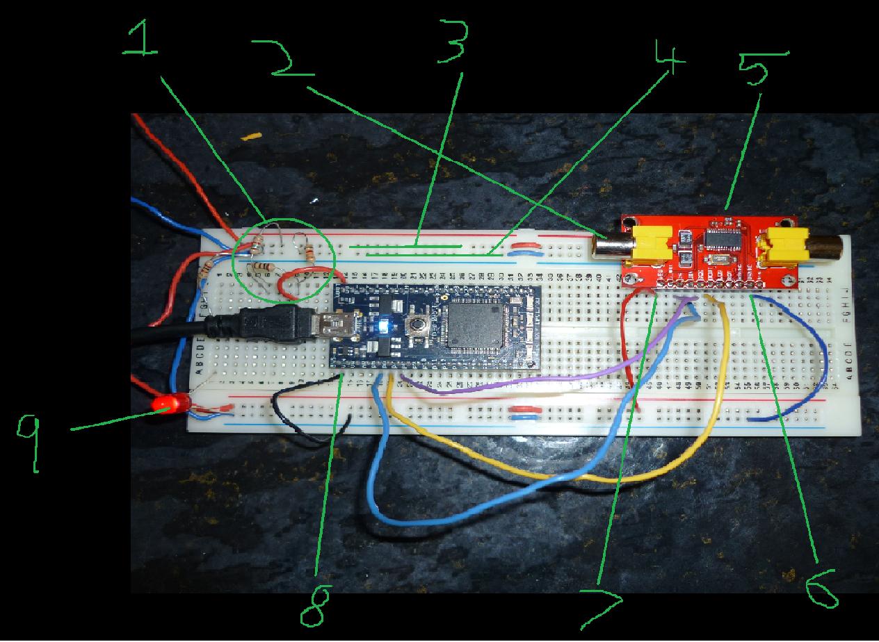
1. This shows a potential divider that gives off 3.3V from the 5V supply rail
2. MAX7556 Module socket for the lead
3. 5V supply rail
4. 0V supply rail
5. MAX7556 Module
6. Wire connected to 0V
7. Wire connected to 5V
8. Wire connected to 0V
9. LED showing that the supple voltage is on
The yellow, purple, blue wire connected between the MAX7556 Module are there for the data input, data output, and the clock input. This is shown in the next diagram below.
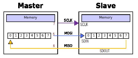
As mentioned before the Master is the mbed and the Slave is the MAX7456, the first step that I had to achieve was to read and write to all the registers with in the slave unit and then create my own functions read and to write. This unsurprisingly didn't work the first time because of a few hardware problems at first. The mbed could be powered up from the USB cable, so I decided to move the power supply, also I added two more wires that represent the chip select(cs) and the reset(rst). Because there was no chip select was not off from the beginning, none of the data was sent there fore none of the data was sent back. Which was why I read the 0x0 value on the terminal. The reset was add to control the device from the beginning.
Once this was achieved my next step was to try and get a character onto the screen now since my read/write operations work. Reading through the data sheet I found that the following registers I needed to write to were the DMDI to locate the default characters, register DMAL to locate the character onto the screen, and VM1 to set the back ground gradient.
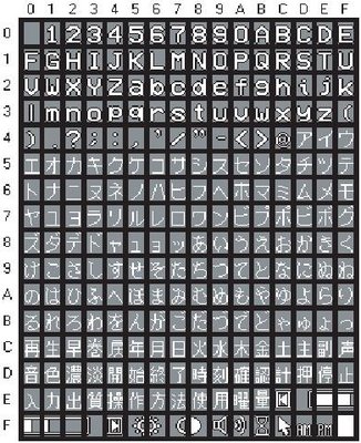
The table above shows what the following characters are. In this test I am trying to write the character "r" to the screen so the command will be 0x36 to the DMDI register.
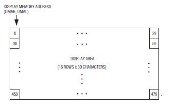
This diagram shows the Display area which is split up into 479 locations, each location is reperesented by a 9-bit word from DMAH to DMAL which is 16-bits altogether.
Once this was done I had nothing happened on the screen. There fore I then read the through all the register tables and realized that I forgot to set the whole module to PAL mode in the VM0 register. Also I had to write to the DMAH to set the mode of the module so that it reads and writes the character address byte rather than the character attribute byte.
After this I have managed to get something onto the screen.
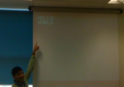
After this I tried to achieve creating "hello world!" onto the screen.
I managed to get the message on the screen how ever some of it didn't quite appear. There fore I had to add in the VOS and HOS(vertical and horizontal offset) to match the whole grid onto the screen.
Once this was done I managed to locate the message hello world on the top left hand corner of the screen.
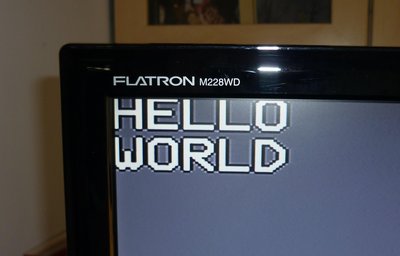
here is a clearer image on my tv screen.
Now since I am able to create any piece of text any where on the screen, I had to create my own library so that it is easier to program.
The following functions had to be included such as:
PutC, locate, format, clear, vertical trim, horizontal trim and of course the read and write function.
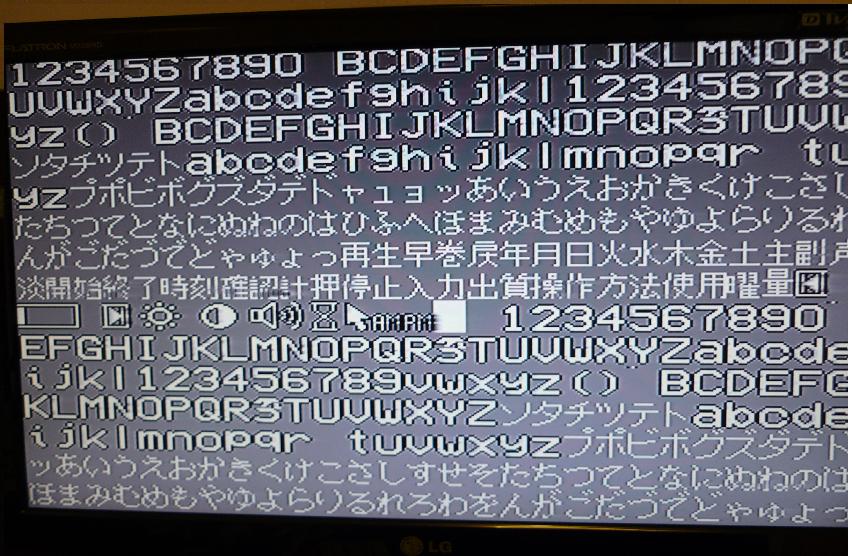
trying out the putc function and the locate function, I tested whether I could see every character in every locations, which worked successfully.
I then had to see whether the printf would work, so I tried to print out "hello world" onto the screen but to do it by using the printf() function this function is linked with the putc function. A string is entered into the printf() and then each character from that string is put into an array where the putc comes in to pick each character and then writes it onto the screen.
The problem is that only the last character of the string seems to appear onto the screen.
what is meant to happen is that, I give one location and then the location should automatically be incremented every time to the right, there fore we should see the whole string on the screen.
I then added an increment function that would increment every x location until it reaches 30 then x location resets to 0 and the y location is incremented. This function that called the location function. Then the whole location function was called at the end of putC function.
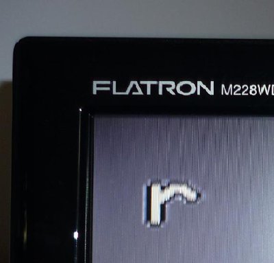
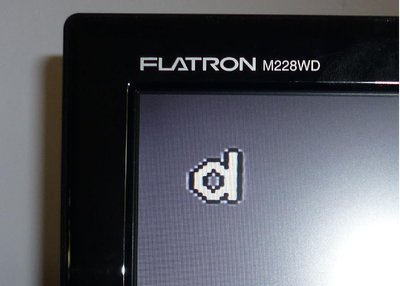
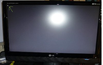
But unfortunately I still couldn't see a hello world on the screen, instead I can only see a part of a character in the top left hand corner. As pointed with the green arrow.
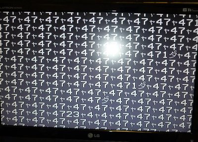
After reading through the data sheet of the MAX7456, I realised that I had missed an important bit of information with in the DMM register. Because I am trying to show a string on the tv screen, it is automatically sending a number of SPI commands quite rapidly which means that the auto_increment mode with in the module most be enabled to cope with a number of SPI commands at a really fast rate which explains why I didn't get much on the screen.
How ever the outcome this time was a lot more dodge.
0 comments
You need to log in to post a comment
MAX7456 Video Overlay
Creating text onto a PAL screen
Page owner:  Liam Faruq
Created 22 Jul 2010.
Last updated 27 Aug 2010