Radio FM TEA5767
Introduction
The TEA5767 is a cheap FM receiver that is controlled through the I2C bus.
The radio can be tuned to the European, US, and Japanese FM bands
Required Components
- mbed
- module TEA5767 (datasheet)
- audio 3.5mm plug jack
Product Specifications
- Input Voltage 3.3V
- I2C (required 10k pull-up resistrors)
- 32.768 kHz clock crystal
Pin Description
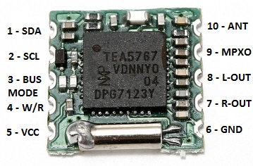
| Name | TEA5767 pin | MBED pin |
|---|---|---|
| SDA | 1 | P28 |
| SCL | 2 | P27 |
| BUSMODE | 3 | GND |
| W/R | 4 | NC |
| VCC | 5 | VOUT |
| GND | 6 | GND |
| R-OUT | 7 | -- |
| L-OUT | 8 | -- |
| MPXO | 9 | NC |
| ANT | 10 | -- |

Schematic

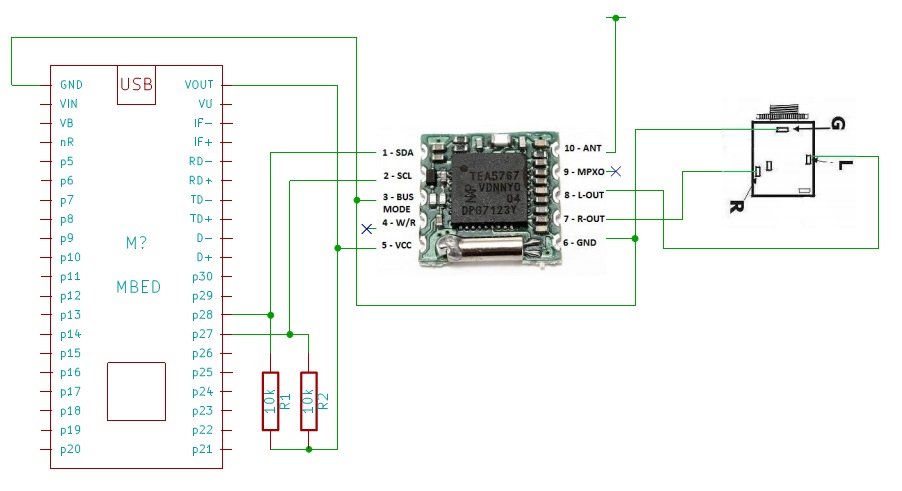
For the antenna I have use a piece of wire.
How it works
The superheterodyne receiver works in this mode: the signal from the antenna is filtered and amplified, then the signal is mixed with a sine wave pruduced from a local oscillator (LO) that shift it to a specific intermediate frequency (IF). The IF signal is itself filtered and amplified and possibly processed in additional ways. The demodulator uses the IF signal rather than the original radio frequency to recreate a copy of the original information.

For more info read this wiki page.
The Frequency is calculated by the following formula that return a 14bits word:

I2C Registers
The writing address of this device is 0x60 and it is controlled by five bytes registers.
Write mode:
Description of 1st data byte
| Bit | Symbol | Description |
|---|---|---|
| 7 | MUTE | if MUTE = 1 then L and R audio are muted |
| 6 | SM | Search mode: if SM = 1 then in search mode; if SM = 0 then not in search mode |
| 5-0 | PLL[13:8] | setting of synthesizer programmable counter for search or preset |
Description of 2nd data byte
| Bit | Symbol | Description |
|---|---|---|
| 7-0 | PLL[7:0] | setting of synthesizer programmable counter for search or preset |
Description of 3rd data byte
| Bit | Symbol | Description |
|---|---|---|
| 7 | SUD | Search Up/Down: if SUD = 1 then search up; if SUD = 0 then search down |
| 6-5 | SSL[1:0] | Search Stop Level: [0-1] = low, [1-0] = mid, [1-1] = high |
| 4 | HLSI | High/Low Side Injection: if HLSI = 1 then high side LO injection; if HLSI = 0 then low side LO injection |
| 3 | MS | Mono to Stereo: if MS = 1 then forced mono; if MS = 0 then stereo ON |
| 2 | MR | Mute Right: if MR = 1 then the right audio channel is muted and forced mono |
| 1 | ML | Mute Left:if ML = 1 then the left audio channel is muted and forced mono |
| 0 | SWP1 | - |
Description of 4th data byte
| Bit | Symbol | Description |
|---|---|---|
| 7 | SWP2 | - |
| 6 | STBY | Standby: if STBY = 1 then in Standby mode; if STBY = 0 then not in Standby mode |
| 5 | BL | Band Limits: if BL = 1 then Japanese FM band; if BL = 0 then US/Europe FM band |
| 4 | XTAL | Clock frequency: Reg PLLREF=0 and XTAL=1 clocl freq=32.768KHz |
| 3 | SMUTE | Soft Mute: if SMUTE = 1 then soft mute is ON |
| 2 | HCC | High Cut Control: if HCC = 1 then high cut control is ON |
| 1 | SNC | Stereo Noise Cancelling:if SNC = 1 then stereo noise cancelling is ON |
| 0 | SI | - |
Description of 5th data byte
| Bit | Symbol | Description |
|---|---|---|
| 7 | PLLREF | see the reg XTAL |
| 6 | DTC | if DTC = 1 then the de-emphasis time constant is 75µs; if DTC = 0 then the de-emphasis time constant is 50µs |
| 5-0 | - | - |
Read mode:
Description of 1st data byte
| Bit | Symbol | Description |
|---|---|---|
| 7 | RF | Ready Flag: if RF = 1 then a station has been found or the band limit has been reached |
| 6 | BLF | Band Limit Flag: if BLF = 1 then the band limit has been reached |
| 5-0 | PLL[13:8] | setting of synthesizer programmable counter for search or preset |
Description of 2nd data byte
| Bit | Symbol | Description |
|---|---|---|
| 7-0 | PLL[7:0] | setting of synthesizer programmable counter for search or preset |
Description of 3rd data byte
| Bit | Symbol | Description |
|---|---|---|
| 7 | STEREO | Stereo indication:if STEREO = 1 then stereo reception; if STEREO = 0 then mono reception |
| 6-0 | IF[6:0] | IF counter result |
Description of 4th data byte
| Bit | Symbol | Description |
|---|---|---|
| 7-4 | LEV[3:0] | level ADC output |
| 3-1 | CI[2:0] | Chip Identification: these bits have to be set to logic 0 |
| 0 | - | - |
Description of 5th data byte
| Bit | Symbol | Description |
|---|---|---|
| 7-0 | - | - |
Test Code
Import programTEA5767_RadioFM_Test_Code
Test Code for TEA5767 radio module
Library
Import libraryTEA5767
Library for TEA5767 FM stereo radio module
C# Program
You can download the program here: RadioFM v1.0
Is required Microsoft .NET Framework 3.5 or above.
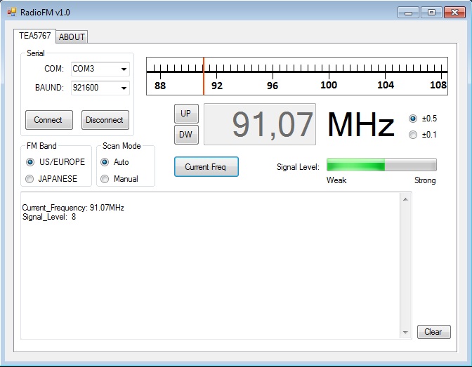
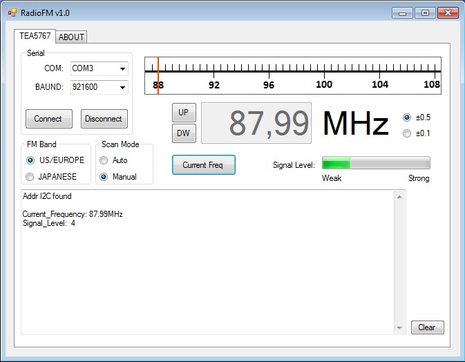
Some screens:


Please log in to post comments.
