TLC5940 Servo Controller
The TLC5940 Driver
The TLC5940 is a 16-channel, constant-current sink LED driver. Each channel has an individually adjustable 4096-step grayscale PWM brightness control and a 64-step, constant-current sink (dot correction). While the chip is marketed specifically as a LED driver, the grayscale PWM control can be used to turn this device into a generic PWM expander to drive any number of PWM devices as long as they all have the same PWM period. Additiotally, these drivers can easily be daisy chained to increase the number of PWM outputs. This makes this device perfect for creating a general purpose PWM expander for Servo motors, which usually require a fixed 20ms period and a lot of PWM outputs.
Regarding Constant-Current Sink
Since this driver uses a constant-current sink, the outputs need to be pulled up to VCC. This also means that the PWM output will be "inverted". We can easily fix this by taking our desired pulse width scaled as a 4096 step int and manually inverting it by doing inv_pw = 4095 - desired_pw. If you already know this, then great. However, it confused me the first time I looked at an oscilloscope reading of my PWM output and all of my output PWs were not what I expected them to be, so hopefully this information helps someone.
TLC5940NT vs Sparkfun TLC5940 Breakout
You can use either a regular TLC5940NT DIP or the TLC5940 Breakout from Sparkfun. They both use the same chip and will work exactly the same. I will go over wiring both of these chips as I used both of them during my development. XERR is ignored in both cases because I am not checking for errors. SOUT is also ignored because I am not daisy chaining.
Note Regarding External Power
Servos use a lot of current, most likely more current than the mbed can supply, so it is a good idea to use a external power of some sort to drive the servos instead of the mbed's VU (I'm using 4 AA batteries). Remember when using an external power to tie the grounds of the mbed and the external power supply together but DO NOT TIE THE POWER PINS TOGETHER! This could kill your mbed.
TLC5940NT

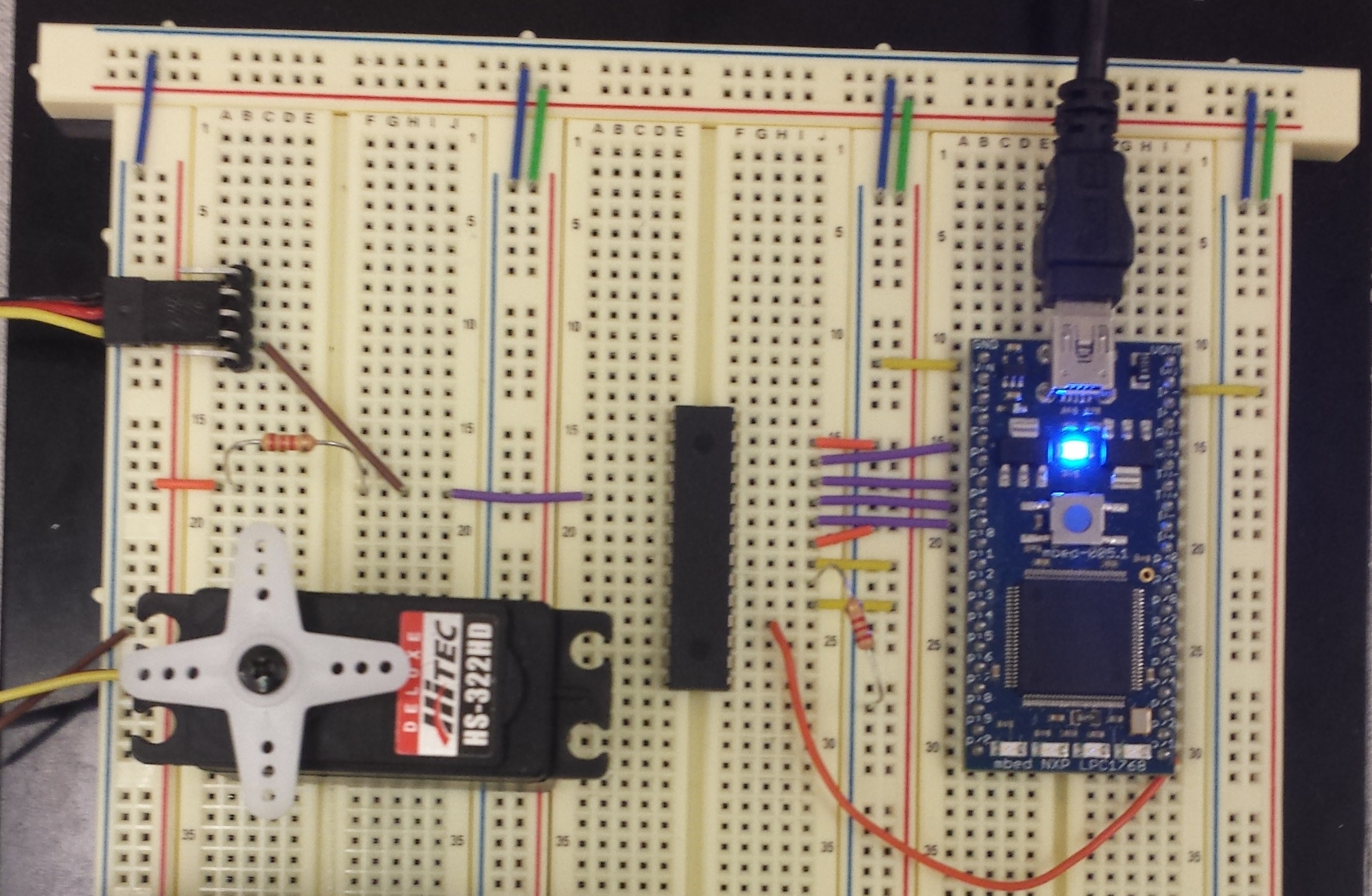
The TLC5940NT is the basic DIP package provided by TI. This chip has support for both grayscale PWM and 64 step dot correction. Since we are interested in driving Servos, the control pins VPRG and DCPRG will be manually pulled to GND and VCC respectively to enable grayscale PWM and disable dot correction. 2.2kΩ resistors must also be added to pull the PWM outputs up to VCC in order to drive the Servo motors. An additional 2.2kΩ resistor is needed to pull the IREF pin down to GND or the chip will not work. All of these resistors are needed, although they don't have to be 2.2kΩ. I use 2.2kΩ simply because that is what the Sparkfun breakout uses.
Wiring TLC5940NT
| TLC5940NT | mbed |
|---|---|
| VPRG | GND |
| SIN | p5 |
| SCLK | p7 |
| XLAT | p8 |
| BLANK | p9 |
| GND | GND |
| VCC | VU |
| IREF | 2.2kΩ to GND |
| DCPRG | VU |
| GSCLK | p21 |
| SOUT | NC |
| XERR | NC |
| OUT0-15 | 2.2kΩ to 5V External |
Note
Servo PWM connects between OUTX and the 2.2kΩ resistor. See picture below. Also note that my external power supply (not shown) is using the leftmost power bus, tying the grounds together while keeping the VCC's separate.

TLC5940 Breakout

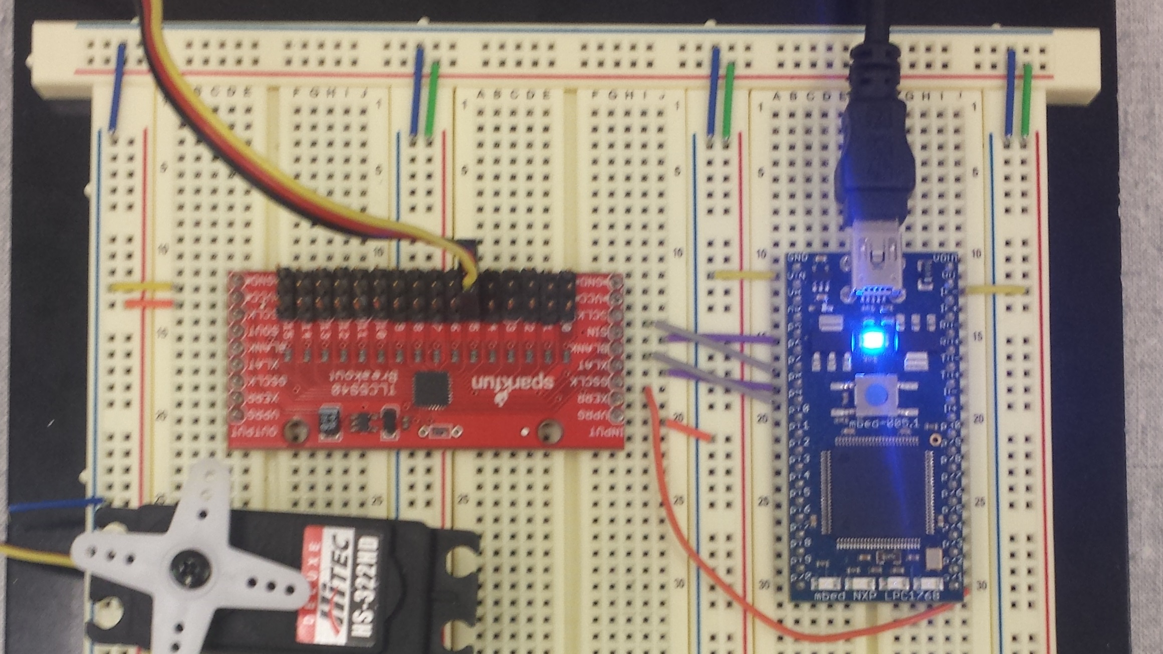
The TLC5940 Breakout is a breakout developed by Sparkfun to make the TLC5940 more Servo friendly. This chip only has support for grayscale PWM and already has 2.2kΩ resistors to pull the PWM outputs up to VCC in order to drive the Servo motors as well as the additional 2.2kΩ resistor to pull the IREF pin down to GND.
Wiring the TLC5940 Breakout
| TLC5940 BOB | mbed |
|---|---|
| VPRG | GND |
| XERR | NC |
| GSCLK | p21 |
| XLAT | p8 |
| BLANK | p9 |
| SIN | p5 |
| SCLK | p7 |
| VCC | 5V External |
| GND | GND |
| Right Side | NC |
Note
Again, note that my external power supply (not shown) is using the leftmost power bus, tying the grounds together while keeping the VCC's separate.

Hello World
Library
Import libraryTLC5940Servo
Library for using the TLC5940 as a servo controller.
Please log in to post comments.
