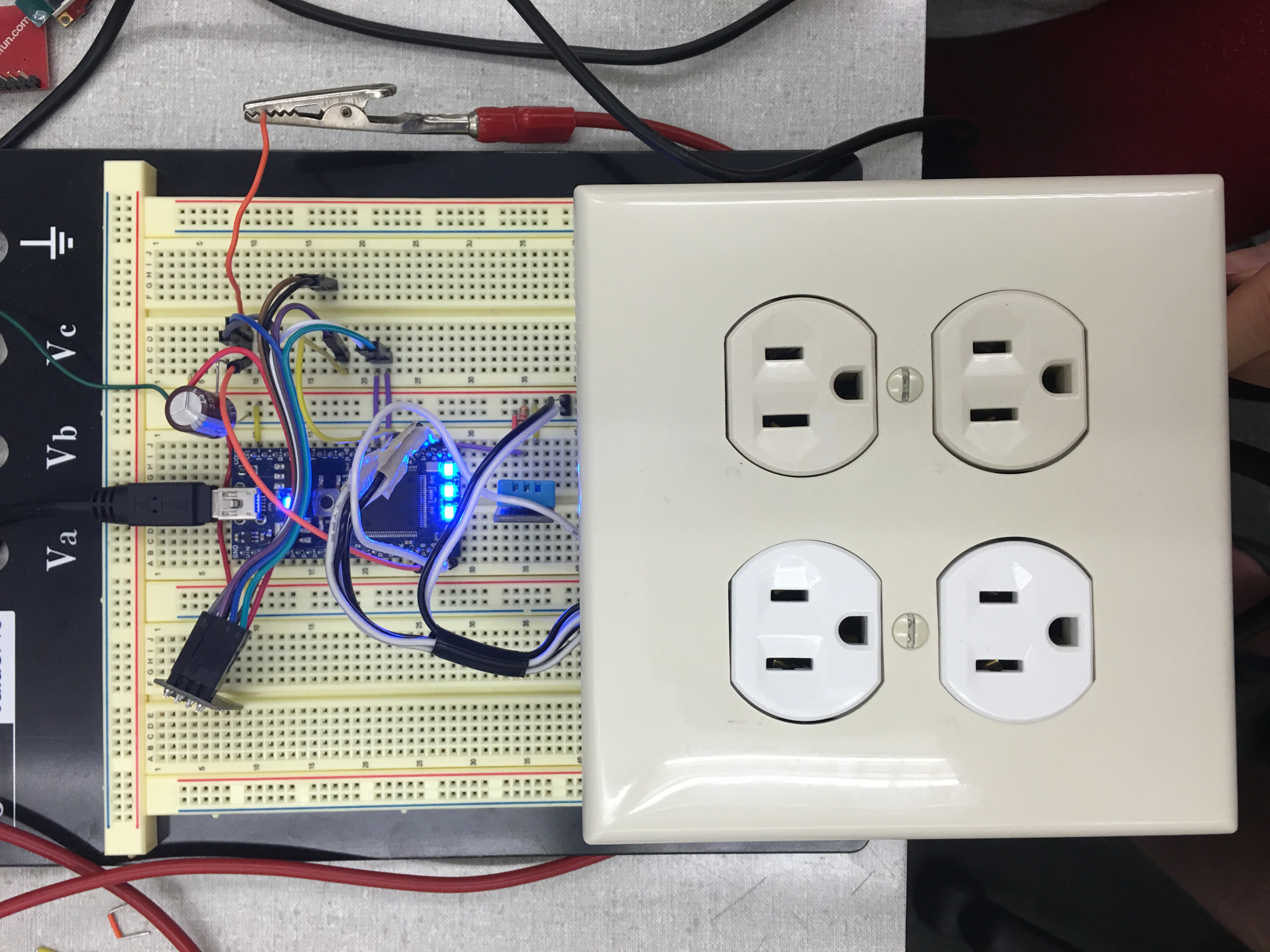
IoT Controlled AC Outlets
 Picture of entire project, showing mbed, ESP-8266, DHT-11, and Outlet box with 4-Channel Relay Board and Current Sensor
Description
Using the mbed, a DHT11 Temperature sensor, an ESP-8266 Wi-Fi Module, a 4 channel relay board, and an AC/DC current sensor, we assembled a device to accomplish the following:
- Control Outlets' ON/OFF functionality via a web interface.
- View current ON/OFF status of each relay.
- Enable thermostat control of a single outlet to enable AC Units and Space heaters to be selectively activated depending on room temperature and set temperature.
- Measure and display current draw and power usage for at least one outlet (Outlet 1 in our case).
Group Members: Alex Davidson and Deron Mai
Hookup Guide
For this device to work, the ESP-8266 Wi-Fi Module, DHT11, Relays, and Current Sensor will need to be properly connected to the mbed:
ESP-8266 Wi-Fi Module
| mbed | ESP-8266 | 3.3V Power Supply | 330uF Cap. |
|---|---|---|---|
| GND | GND | GND | (-) |
| Vcc | V+ | (+) | |
| p26 | RESET | ||
| p28(TX) | RX | ||
| p27(RX) | TX | ||
| Vout | CH-PD |
Note: Vcc connection for ESP-8266 must be powered by an external supply. The mbed's internal 3.3V supply cannot provide the power necessary for Wi-Fi Transmissions. Also a 330uF decoupling capacitor should be connected across the Vcc and GND lines of the Wi-Fi module to prevent sudden voltage drops.
DHT-11 Temperature Sensor
| mbed | DHT-11 |
|---|---|
| GND | GND (-) |
| p21 | Signal |
| Vu | Vcc (+) |
Note: p21 or Signal line must have a 4.7k-5.1k pull-up resistor connected to 5V.
4-Channel Relay Board
| mbed | Relay Board | 5V Power Supply |
|---|---|---|
| GND | GND | GND |
| Vcc | V+ | |
| p22 | IN1 | |
| p23 | IN2 | |
| p24 | IN3 | |
| p25 | IN4 |
Note: Each relay will be also connected to AC Power Cable (HOT) and each Outlet (HOT) terminal. Note: An external 5V power supply is recommended to support the current draw from the relay board although the mbed's Vu(5V) pin may work.
AC/DC Current Sensor
| mbed | Currrent Sensor |
|---|---|
| GND | GND (-) |
| p20 | Signal |
| Vu | Vcc (+) |
Note: The AC/DC Current Sensor must be connected in series with Relay 1 AC (-) and Outlet 1 (HOT) terminal. This will allow the current sensor to measure how much current is flowing through Outlet 1.
Images
Screenshot of Webserver page run by ESP-8266. Shown are controls for each outlet and measurements for 3.3V Power Supply, and Output1 current.

Video of Device in Action
Code & Libraries
Import programECE4180_Lab4_ESP8266_IoT_Outlets
iot init pub
1 comment on IoT Controlled AC Outlets:
Please log in to post comments.

hello. Can you help me?
--ESP8266 Hardware Reset----Received temp is: 0.000
RTC time 00:00:00 Fri 01 Jan 66
++++++++++ Resetting ESP ++++++++++ 0 ++++++++++ ESP8266 error, check power/connections ++++++++++