RFID Door Lock
Overview
Import programRFIDdoor
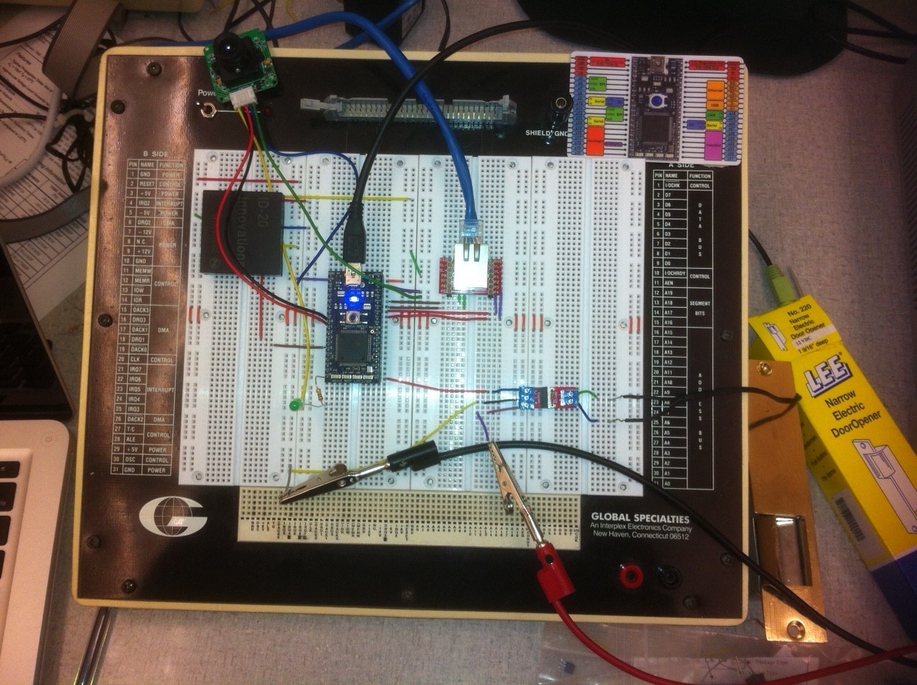
RFID door access with security camera
The Mbed may be used to make a door lock using RFID access. This project involves interfacing an RFID scanner, an internet database of allowable RFID codes, an electric door lock and a Camera to take a picture when access is not granted.
This project reads a RFID tag and checks a database to identify the tag. If the tag is allowed then the door is unlocked. If the tag is not allowed the door stays locked and a camera captures a picture of the person trying to enter. The components used are as follows:
- ID20 RFID scanner
- LS_Y201 Camera
- Sparkfun *Power Controller
- Ethernet Jack
- Electric Door lock.
Photos and Video

Implementation
The project requires internet connectivity to retreive allowable Tag codes from a database. In this case a comma seperated value file with tags in it is used. Ethernet connectivity is used to get the database of RFID codes. When a user scans a card it is compared to the list online and if it is allowed the door lock is opened. If the RFID tag is not found on the list, a red LED is lit and a picture is taken with the camera. This picture is stored on the local storage of the Mbed. After the access decision is made the device returns to the loop and waits for another key to be read. The ID-20 was selected because of its increased range over the ID-12 but the two are interchangable. The pinouts for the ID-12(20) can be found in the cookbook. The door lock used was a Lee Narrow Electric Door Openor that operated at 12V. A sparkfun powercontrol was used to supply the door lock with the 12V from an external power supply. The ethernet was implemented using a MagJack connector from Sparkfun. The Camera used is a LSY-201 TTL serial interface camera with a resolution 640x480. A generic LED was used to show when access was not granted to the RFID tag.
Code
http://mbed.org/users/dburnham6/programs/RFIDdoor/lz0luj
Pinouts
| MBED | Power Control | ID-20 RFID | Camera | Ethernet | LED |
|---|---|---|---|---|---|
| p9(TX) | RX | ||||
| p10(RX) | TX | ||||
| p14(RX) | D0 | ||||
| p21 | Control | ||||
| TD- | P1 | ||||
| TD+ | P2 | ||||
| RD- | P8 | ||||
| RD+ | P7 | ||||
| p20 | Anode | ||||
| VV | VCC/NRST | VCC | |||
| GND | GND/FS | GND | Cathode |
Please log in to post comments.
