API for interfacing with a game cube controller
Gamecube Controller Interface
This is a library to interface the Gamecube Controller to the mbed. The goal of this project is to read input data from the controller.
Introduction
This library lets you read data from a Gamecube Controller. It allows you to use two pins to get 6+ buttons, a D-pad (up/down/left/right), two variable triggers, and two joysticks. The controller was stripped of its connector and this wiki shows the subsequent steps to wire the controller to the mbed and code needed to read data through a serial connection. Assembly was used because the timing for the controller needs to have microsecond accuracy. The shortest wait found using wait_us(...) was 1.5us.
Pinout
| Color | Function |
|---|---|
| Yellow | 5V power supply (rumble) |
| Red | Data: bi-directional / 3.3V |
| Green | Ground |
| White | Ground |
| Blue | 3.3V power supply |
*Note this pinout is for the latest Gamecube controller

Wiring
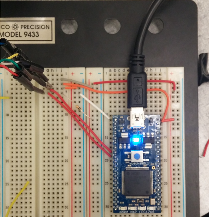
The Gamecube controller was cut to expose the wires. Seperate them and solder other wires on to them for stability and consistency.

| Color (Gamecube) | mbed Pin |
|---|---|
| Yellow | VOUT |
| Red | p9 and p10 |
| Green | Ground |
| White | Ground |
| Blue | VU |

Gamecube Controller Protocol
The Gamecube controller uses 3.3V logic (bidirectional), 3.3V to power the controller, and 5V for the rumble motor.
The 5V power used by the rumble motor is always on, and the motor is controlled by a command sent to the controller.
The controller uses one bi-directional data line to communicate with the console. This is an active high 3.3V logic signal, using a 10K pull-up resistor to 3.3V to hold the line high. Communication is initiated by the console sending a 24-bit string to the controller, after which the controller responds with 64-bits of button state and joystick data.
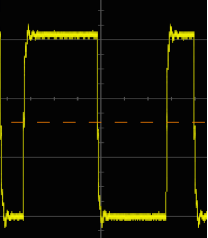
The transfer speed is fast at around 4 microseconds per bit. .A low bit is signaled by a 3us low followed by 1us high, and a high bit is signaled by 1us low followed by 3us high.
Here is a 0 followed by a 1

The last bit of the command is the 'rumble' control. Setting this bit to one enables the rumble motor, and clearing it disables the motor.
Polling for Data
When the Gamecube or the controller sends a string of bits, it terminates it with a single (high) stop bit. Therefore, in order to send the string 00000000, the Gamecube would send 000000001.
There is a typical interval of about 6ms between successive updates. The real time update time would depend on the game being played or the video frame update rate. The sequence starts with a 24-bit command from the console:
0100 0000 0000 0011 0000 000 (0*) *rumble
After the 24-bit command, the controller responds with a string of bits that contain the state of all the buttons along with joystick position data. The sequence of the returned data is shown in the table below. The buttons are listed in transmission order, from left to right.
| Byte 0 | 0 | 0 | 0 | Start | Y | X | B | A |
| Byte 1 | 1 | L | R | Z | D-Up | D-Down | D-Right | D-Left |
| Byte 2 | Joystick X Value (8 bit) |
| Byte 3 | Joystick Y Value (8 bit) |
| Byte 4 | C-Stick X Value (8 bit) |
| Byte 5 | C-Stick Y Value (8 bit) |
| Byte 6 | Left Button Value (8 bit) |
| Byte 7 | Right Button Value (8 bit) |
Example Code
Basic program to use with library
//
#include "mbed.h"
#include "Gamecube.h"

Serial pc1(USBTX, USBRX); // tx, rx
DigitalOut myled(LED1);
int main() {
    Gamecube g(p9); // gamecube controller connected to pin 9
    int device_id = g.get_device_id();
    if (device_id != NINTENDO_DEVICE_GC_WIRED) { // device id for controller is 0x0900
        pc1.printf("this device is not a nintendo gamecube wired controller!, it returned an ID of %d\n", device_id);
    }
    while(1) {
        g.update();
        pc1.printf("A: %d \n\rB: %d \n\rX: %d \n\rY: %d \n\rL: %d \n\rR: %d \n\rZ: %d \n\rSTART: %d \n\rD_UP: %d \n\rD_LEFT: %d \n\rD_DOWN: %d \n\rD_RIGHT: %d \n\rJOYSTICK_X: %d \n\rJOYSTICK_Y: %d \n\rC_STICK_X: %d \n\rC_STICK_Y: %d \n\rLEFT_TRIGGER: %d \n\rRIGHT_TRIGGER: %d \n\r", g.A, g.B, g.X, g.Y, g.L, g.R, g.Z, g.START, g.D_UP, g.D_LEFT, g.D_DOWN, g.D_RIGHT, g.JOYSTICK_X, g.JOYSTICK_Y, g.C_STICK_X, g.C_STICK_Y, g.LEFT_TRIGGER, g.RIGHT_TRIGGER);
        wait(1);

        g.rumble(true); // rumble working
        myled = 1;
        wait(1);
        myled = 0;
        g.rumble(false);
        wait(.2);
    }
}
Functions
Functions
    // constructor
    Gamecube(PinName _data_line);

    // gets the device id
    int get_device_id();

    // call this to update public variables in header file
    void update(void);
Library
Import programgamecube_controller
API for interfacing with a game cube controller
Demo
gc_asm_write_read.s
- Committer:
- christopherjwang
- Date:
- 2015-12-06
- Revision:
- 1:a93f71ee6778
- Parent:
- 0:7434770d9fc9
File content as of revision 1:a93f71ee6778:
; no attempt to reserve registers!
; void gc_asm_write_read(uint32_t *buff, uint8_t len, uint32_t *read_buff, uint8_t read_buff_len)
; R0-R3 inputs
; R1 and R3 are decremented as the buffers are looped through
; R4 #0x00000001 bit mask for p10
; R5 my personal "temp" register for quick calculations, if not used in succession it should be considered clobbered
; R6 0x2009C020 GPIO port 2 base address
; R7 address offset to write and read from buff and read_buff_len, it increments whenever R0 or R3 decrements


    AREA asm_func, CODE, READONLY
    EXPORT gc_asm_write_read
gc_asm_write_read
    PUSH    {R4-R7, LR}
    SUB     R7, R7, R7

WRITE_LOOP

; Load GPIO Port 1 base address in register R1
    LDR     R6, =0x2009C000 ; 0x2009C020 = GPIO port 1 base address
    MOV.W   R4, #0x00000001   ; 0x040000 = 1<<18 all "0"s with a "1" in bit 18

    LDR     R5, [R0, R7]

    CMP     R5, #0          ; value == 0 ?
    BNE     SEND_HIGH
    STR     R4, [R6,#0x1c]  ; set low
    BL      WAIT_ONE_US_MINUS_OVERHEAD
    BL      WAIT_ONE_US
    BL      WAIT_ONE_US
    B       _END_SEND_HIGH
SEND_HIGH
    STR     R4, [R6,#0x1c]  ; set low
    BL      WAIT_ONE_US
    STR     R4, [R6,#0x18]  ; set high
    BL      WAIT_ONE_US_MINUS_OVERHEAD
    BL      WAIT_ONE_US

_END_SEND_HIGH
    STR     R4, [R6,#0x18]
    BL       WAIT_ONE_US

    SUB     R1, R1, #0x01 ; going through the array backwards (it was reversed in the c layer)
    ADD     R7, R7, #0x04 ; increment address that we access using R7

    CMP     R1, #0
    BLT     FINISH_WRITE
    B       WRITE_LOOP

FINISH_WRITE
    ; send one high bit to terminate
    STR     R4, [R6,#0x1C]  ; set low
    BL       WAIT_ONE_US
    STR     R4, [R6,#0x18]  ; set high
    BL       WAIT_ONE_US_MINUS_OVERHEAD
    ;end of send one high bit to terminate

; begin read

    SUB     R7, R7, R7          ; offset to write into the array given
    SUB     R3, R3, #1
    B       FIRST_READ

READ_LOOP
    SUB     R3, R3, #1  ;R3 is the number of bits to read
    CMP     R3, #0
    BLT     FINISH

    LDR     R5, =0x999999
WAIT_FOR_HIGH
    SUB     R5, R5, #1          ; only check 0x100 times, 0x100 is arbitrarily chosen right now
    CMP     R5, #0
    BEQ     FINISH              ; TODO: add in fail case here!

    LDR     R5, [R6, #0x14]     ; load pin states
    AND     R5, R5, R4          ; get only p10
    CMP     R5, #0
    BEQ     WAIT_FOR_HIGH

    ; wait for 2us to get the bit we want
    BL      WAIT_TWO_US_MINUS_OVERHEAD

FIRST_READ
    LDR     R5, [R6, #0x14]     ; load pin states
    AND     R5, R5, R4          ; get only p10
    CMP     R5, #0
    BEQ     STORE_ZERO
    LDR     R5, =0x01
    STR     R5, [R2, R7]
    BL      WAIT_ONE_US_MINUS_OVERHEAD
    B       END_STORE_ZERO
STORE_ZERO
    LDR     R5, =0x00
    STR     R5, [R2, R7]
END_STORE_ZERO
    ADD     R7, R7, #0x04       ; increment address stored
    B READ_LOOP


FINISH
    POP     {R4-R7, LR}
    BX      LR

WAIT_ONE_US_MINUS_OVERHEAD
    LDR     R5, =0x8
_WAIT_ONE_US_MINUS_OVERHEAD
    SUB     R5, R5, #1
    NOP
    NOP
    NOP
    NOP
    NOP
    NOP
    CMP     R5, #0
    BNE     _WAIT_ONE_US_MINUS_OVERHEAD
    BX      LR

WAIT_ONE_US
    LDR     R5, =0x9
_WAIT_ONE_US
    SUB     R5, R5, #1
    NOP
    NOP
    NOP
    NOP
    NOP
    CMP     R5, #0
    BNE     _WAIT_ONE_US
    BX      LR

WAIT_TWO_US_MINUS_OVERHEAD
    LDR     R5, =0x17
_WAIT_TWO_US_MINUS_OVERHEAD
    SUB     R5, R5, #1
    NOP
    NOP
    NOP
    NOP
    NOP
    NOP
    CMP     R5, #0
    BNE     _WAIT_TWO_US_MINUS_OVERHEAD
    BX      LR


    END
