Important changes to repositories hosted on mbed.com
Mbed hosted mercurial repositories are deprecated and are due to be permanently deleted in July 2026.
To keep a copy of this software download the repository Zip archive or clone locally using Mercurial.
It is also possible to export all your personal repositories from the account settings page.
Dependencies: mbed bmm150GeoMagnetic
You are viewing an older revision! See the latest version
Homepage
BMM150_HelloWorld
Christian Dupaty 03/2021
Library and demo for BMM150 see datasheet here : https://www.bosch-sensortec.com/products/motion-sensors/magnetometers-bmm150/
Adaptation of BOSCH driver https://github.com/BoschSensortec/BMM150-Sensor-API for ARM MBED and tested on NUCLEO-L073RZ and GEOMAGNETIC CLICK https://www.mikroe.com/geomagnetic-click

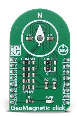
The BMM150 sensor supports I2C and SPI serial communications. The choice of protocol is made on the PS pin (see datasheet page 32), the default mode is SPI. Unfortunately, MIKROE did not place a configuration micro-switch on the GeoMagnetic-click module, but straps that are difficult to move. By default, the module is configured in SPI mode (all the straps are on the left as in the photo). To place the module in I2C mode, all the straps must be moved to the right. However, it is possible to implement I2C communications without moving all the straps: - Move only the strap from the bottom to the right. - On the left connector: - CS is connected to CSB-BMM150 - SCK is connected to SCL-I2C-BMM150 - MISO is linked to SDO-BMM150 - MOSI is connected to SDA-I2C-BMM150
BMM150 DataSheet page 36, CSB and SDO are used to define the I2C address. In the program, this address is chosen in BMM150_defs.h line 37 (here address 0x13, therefore CSB = 1 and SDO = 1)
- define BMM150_I2C_Address (0x13 << 1)
SCL and SDA lines must be connected to 3.3v by pullup resistor (4.4K to 10K) to comply with the I2C standard
Supply with the NUCLEO card in 3.3v and GND