FRDM-KL25Z WiFly Access Point iPhone Android Controlled Zumo RC Tracked Vehicle
Introduction
Note: This page incomplete. I will complete it in few days.
First of all I must tell you that I'm very new to mbed platform, I started to write code with mbed 2-3 weeks ago. Also I'm not a native English speaker. For that reason, please forgive my grammatical and engineering related mistakes and please let me know about them.
I had some unused parts at home and I decided to use them to make a RC tracked vehicle with them. I liked the mbed platform so much, so I decided to used mbed for the job. I bought and used FRDM-KL25Z with mbed for the project. At the end the project turned out to be a very stable and very fun RC vehicle project with iPhone and Android controller.
I didn't see any examples about making WiFly module works as an access point and saw some questions about this. Therefore, I decided to write a step by step tutorial about this complete project. I think many steps of this tutorial will be seen very easy for most of developers in this community, so I tried to divide the tutorial in many steps so you can skip the ones that you don't need. Hope this tutorial will be helpful to you.
Here are some pictures about the project:
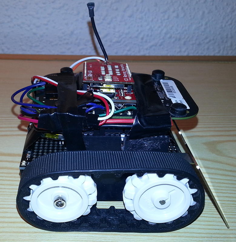
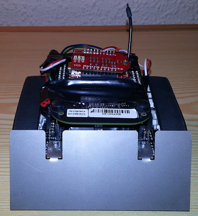
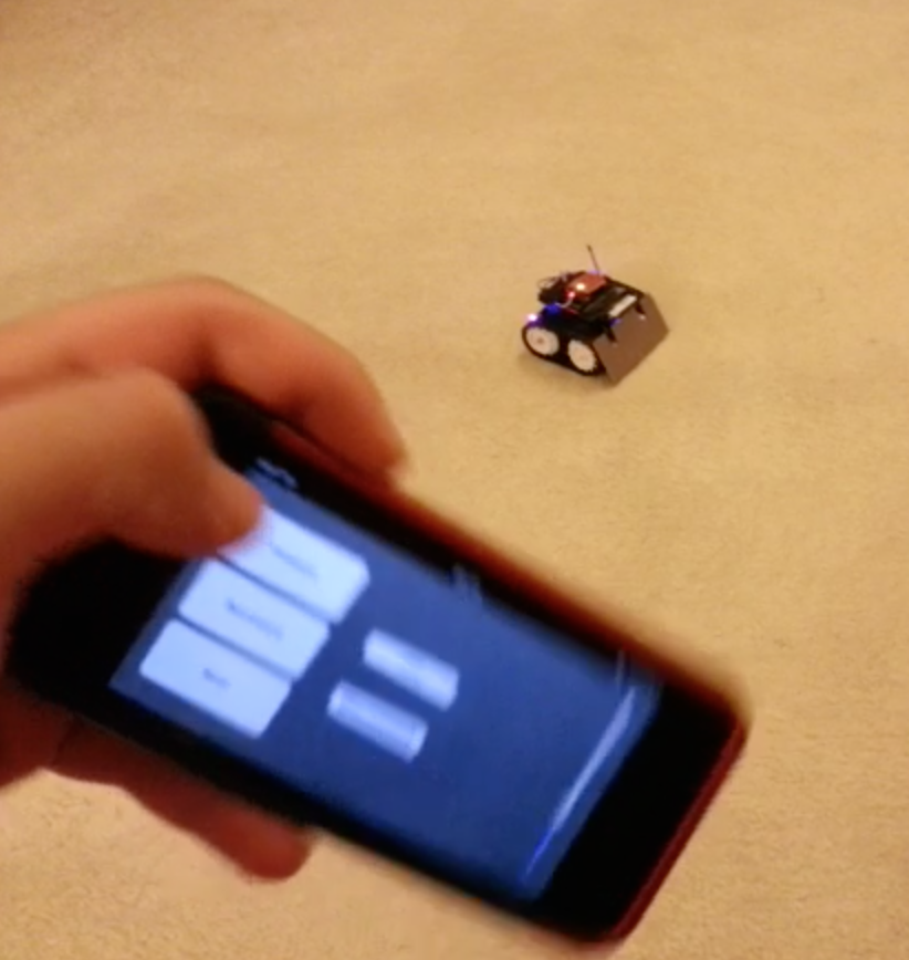
Required Parts:
- FRDM-KL25Z (mbed) (http://uk.farnell.com/jsp/displayProduct.jsp?sku=2191861&action=view&CMP=GRHS-1000684)
- Pololu Zumo Robot Kit For Arduino (http://www.pololu.com/catalog/product/2505)
- 2 x Pololu HP Metal Gear Motors. Can be:
- 50:1 micro HP (http://www.pololu.com/catalog/product/998)
- 75:1 micro HP (http://www.pololu.com/catalog/product/2361)
- 100:1 micro HP (http://www.pololu.com/catalog/product/1101)
- 150:1 micro HP (http://www.pololu.com/catalog/product/997)
- I used 75:1 micro HP motors, which are in my opinion the best fit for Zumo in terms of speed and torque. In fact you can buy any micro HP motor you like and make the Zumo very fast or very high torque.
- WiFly Module. I used:
- RN-XV WiFly Module - Wire Antenna (https://www.sparkfun.com/products/10822)
- For making the wiring between FRDM and WiFly simpler, you can choose one of these:
- Breakout Board for XBee Module (https://www.sparkfun.com/products/8276)
- XBee Explorer Regulated (https://www.sparkfun.com/products/11373)
- XBee Explorer USB (https://www.sparkfun.com/products/8687)
- I used XBee Explorer USB because I had one but if you need to buy one, I would prefer "Breakout Board for XBee Module" because I will use 3.3V (VCC), GND, DIN and DOUT pins for this project. You don't need a regulated voltage or USB for WiFly Module.
- Battery. Your choices are:
- Use four AA Alkaline, NiMH or Li-ion batteries and place it inside Zumo's battery holder.
- Use 7.4V LiPo battery and connect it externally. I bought a LiPo battery from one of the local electronics shop similar to this one: http://www.ebay.com/itm/NEW-Great-Planes-LiPo-2S-7-4V-1000mAh-Novus-200-FP-GPMP0411-NIB-/290904992331?pt=US_Radio_Control_Control_Line&hash=item43bb49ea4b. If you buy a LiPo battery with size like this, you can hide the battery between FRDM and Zumo shield like I do. Keep that in mind that you can apply maximum 9V to the motors and also FRDM's Vin supports 4.3V-9V power input. For that reason, you can choose any battery or batteries that gives an output voltage between 4.3V-9V.
- Arduino Stackable Header Kit (https://www.sparkfun.com/products/10007) (If you want to use the Zumo blade, you will need this header kit)
1. Assembling Zumo:
For assembling Zumo, all you need to do is follow this step by step guide from Pololu:
Next to Arduino pinouts, there are 2 other pinout lines which are connected o the same pins. I soldered some headers to these pins too for connecting jumpers easily later. Because FRDM will be connected to Zumo shield upside down, unless you use stackable female headers for FRDM pins, you won't access any other FRDM pins and you need to access the pins in order to connect the WiFly Module. You can examine the pictured of my Zumo RC system to understand this better.
2. Understanding Zumo Shield:
There is a nice schematics documentation about the shield here: http://www.pololu.com/file/0J591/zumo_shield_schematic.pdf.
Zumo Shield consists of:
1. TI DRV8835 Dual Motor Driver
- Motor supply voltage: 2–11 V
- Logic supply voltage: 2–7 V
- Output current: 1.2 A continuous (1.5 A peak) per motor
2. Piezo Buzzer
Piezo buzzer can be controlled with PWM output.
3. LSM303DLHC I²C 3-axis accelerometer and 3-axis magnetometer
- Operating voltage: 2.5 to 5.5 V
- Supply current: 10 mA
- Output format (I²C):
- Accelerometer: one 12-bit reading (left-justified) per axis
- Magnetometer: one 12-bit reading (right-justified) per axis
- Sensitivity range (configurable):
- Accelerometer: ±2, ±4, ±8, or ±16 g
- Magnetometer: ±1.3, ±1.9, ±2.5, ±4.0, ±4.7, ±5.6, or ±8.1 gauss
4. Pushbutton
5. 7.5 V boost regulator for powering the FRDM from the Zumo’s 4 AA batteries
6. LED
7. General-purpose prototyping areas and an expansion area at the front for connecting additional sensors
- There is a fron expansion area pinout documentation here: http://www.pololu.com/file/0J592/zumo_shield_front_expansion_pinout.pdf.
Pinouts and Jumpers
When you connect the FRDM properly (by placing it with considering 6-8-8-10 headers) pinouts are given below:
| Description | FRDM Pin |
|---|---|
| Right Motor Direction | PTC9 |
| Left Motor Direction | PTA13 |
| Right Motor PWM | PTD5 |
| Right Motor PWM | PTD0 |
| Buzzer Choice 1 | PTC8 |
| Buzzer Choice 2 | PTA12 |
| 3-axis accelerometer-magnetometer SDA | PTE0 |
| 3-axis accelerometer-magnetometer SCL | PTE1 |
- Piezzo buzzer and 3-axis accelerometer-magnetometer are *NOT* connected to the given pins above initially. You need to connect specific jumpers for this. Description of jumpers are given in the below picture:
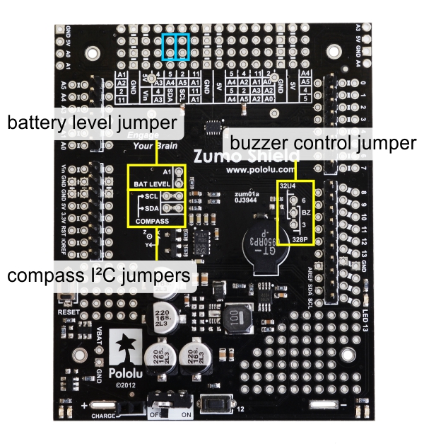
3. Connecting FRDM to Zumo Shield:
Since Zumo shield is designed for Arduino UNO or Leonardo and FRDM is a little longer than Arduino UNO or Leonardo, if you assemble the Zumo blade to Zumo chassis, FRDM doesn't fit to Zumo Shield. You need to lever up your FRDM to make it fit to Zumo Shield. For that reason, I placed an Arduino Stackable Header Kit (https://www.sparkfun.com/products/10007) between FRDM and Zumo Shield.
4. Upgrading WiFly Firmware
For making WiFly an Access Point you need a WiFly Firmware 4.0 or higher. Roving Networks has a very nice User's Guide documentation which includes every command set that I will use here and so much more: /media/uploads/can90/rn-wiflycr-ug-v1.2r.pdf
For connecting WiFly to your computer and communicate with its serial port, you can use this code:
Import programWifly_configure
Configure wifly module
written in the mbed WiFly Interface handbook: http://mbed.org/cookbook/WiflyInterface and connect the WiFly to your computer through mbed, or you can buy Xbee Explorer USB (https://www.sparkfun.com/products/8687) and connect it very easily to your computer or you can choose a different method. Just keep that in mind that WiFly uses 9600 baud rate if you haven't changed it. Also I suggest you to use Tera Term for Windows and CoolTerm for Mac OS X for sending and receiving commands.
After making the connection, first check your WiFly's firmware. If your WiFly's firmware is 4.0 or higher, then you won't need to upgrade your firmware. For checking your WiFly's firmware and upgrading the firmware you can apply the commands in the below table one by one:
| Command | Description |
|---|---|
| $$$ | Enter Command Mode |
| scan 10 | scan available wireless network |
| set wlan ssid <ssid> | set wireless ssid to join@ |
| set wlan auth <auth#> | set authentication mode@@ |
| set wlan phrase <phrase> | set wlan password@@@ |
| set wlan join 1 | set join wireless network automatically |
| set ip local 2101 | set listen port number |
| set ip protocol 2 | set protocol to TCP IP |
| save | Save settings |
| reboot | Reboot module |
| $$$ | Enter Command Mode |
| set ftp address 0 | Redirect the module to the new IP address |
| set dns name rn.microchip.com | Enter new IP Address |
| save | Save settings |
| ftp update | Upgrade WiFly's Firmware |
| factory RESET | Reset the module to the factory default state |
| reboot | Reboot module |
@ Replace <ssid> with your wireless network name
@@ Replace <auth#> with:
- 0 for Open (Default)
- 1 for WEP-128
- 2 for WPA1
- 3 for Mixed WPA1 and WPA2-PSK
- 4 for WPA2-PSK
- 5 for Not used
- 8 for WPE-64
@@@If you use WPA type for authentication, you will need to use set wlan phrase <phrase>. If you use WEP type for authentication, you will need to use set wlan key <key>. You need to replace <phrase> or <key> with your wireless network's password.
- Note that, after entering the command "ftp update", you should wait for WiFly to download the firmware and update itself. This process will be shown in serial communication window. If this process fails, don't work and enter "factory RESET" command, you can use your WiFly module like you always do without any difference. Also let me know about any problem that you face about updating your WiFly module's firmware. I will try my best to solve it.
- I used this method to upgrade two WiFly modules (RN-XV WiFly - Wire Antenna and RN-XV WiFly - RPSMA) without any problem.
5. Connecting WiFly to FRDM
You only need rx/tx pins to connect the WiFly Module to FRDM. You can choose any Serial rx/tx pin for that. Serial rx/tx pins are indicated in Pinouts documentation of mbed:
http://mbed.org/handbook/Pinouts
I also connected reset and TCP connection indicator pins just for making the hardware compatible with the Wifly class, which can be found in WiflyInterface Library:
Import libraryWiflyInterface
mbed official WiflyInterface (interface for Roving Networks Wifly modules)
You will only need Wifly folder in WiflyInterface library for this project. Aster giving the necessary information, here is my preferred setup for connecting WiFly Module and FRDM mbed:
| WiFly Pin | FRDM Pin |
|---|---|
| VCC | P3v3 |
| GND | GND |
| RX(DIN) | PTD3 |
| TX(DOUT) | PTD2 |
| RESET | PTC8 |
| GPIO6 | PTC7 |
6. Powering the System
You have
- You can use 4 AA batteries for this. Place the batteries inside your Zumo's battery holder. Batteries can be Alkaline or rechargeable type. Zumo's battery holder connects them serially.
- You can use a LiPo, Li-Ion or any other type of battery that you prefer and connect the battery's "+" and "-" outputs to Zumo Shield's batter charge connector pins. You can see where those pins are located on Zumo Shield by looking at the below image:
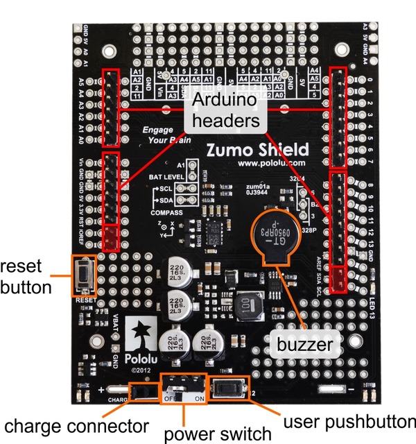
Be careful while connecting the battery. Pay attention to "+" sign near battery charging connector pins on Zumo Shield to connect the battery in a right way.
7. FRDM-KL25Z mbed Code
You can find the code at this link:
Import programFRDM-KL25Z_WiFly_Access_Point_Mode_Zumo_RC
FRDM-KL25Z WiFly Access Point iPhone Android Controlled Zumo RC Tracked Vehicle mbed Code
I will try to explain the code briefly.
8. iPhone Application Code
9. Android Application Code
10. Complete System User Guide
1 comment on FRDM-KL25Z WiFly Access Point iPhone Android Controlled Zumo RC Tracked Vehicle:
Please log in to post comments.

Could you explain how do you sent data from iPhone/Android to RN-XV WiFly Module?