Screamer
 Brennon Farmer.
0
replies
Brennon Farmer.
0
replies
Team Members
Brennon Farmer, Carter Montgomery, William Rose
Project Overview
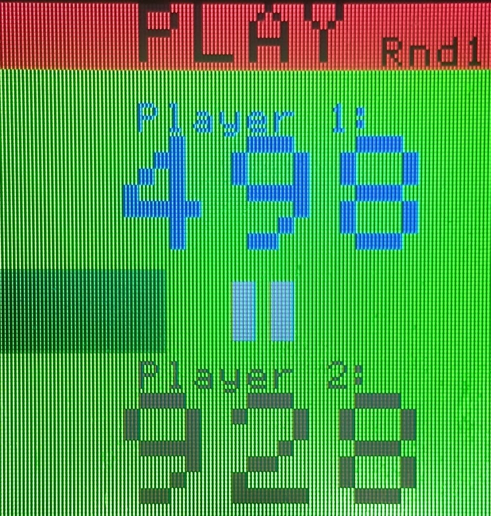
The purpose of the project is to allow two people to play a game by screaming into two microphones. Based on the loudness of each player's voice, individual LEDs of a LED strip will be turned on. The color of the LED depends on which player's voice caused the LED to turn on. The player that turns on the most LEDS in a certain time limit or turns on all the LEDs will be the victor. Two microphones will be used to record the audio and convert to an analog value for the two players' voices.
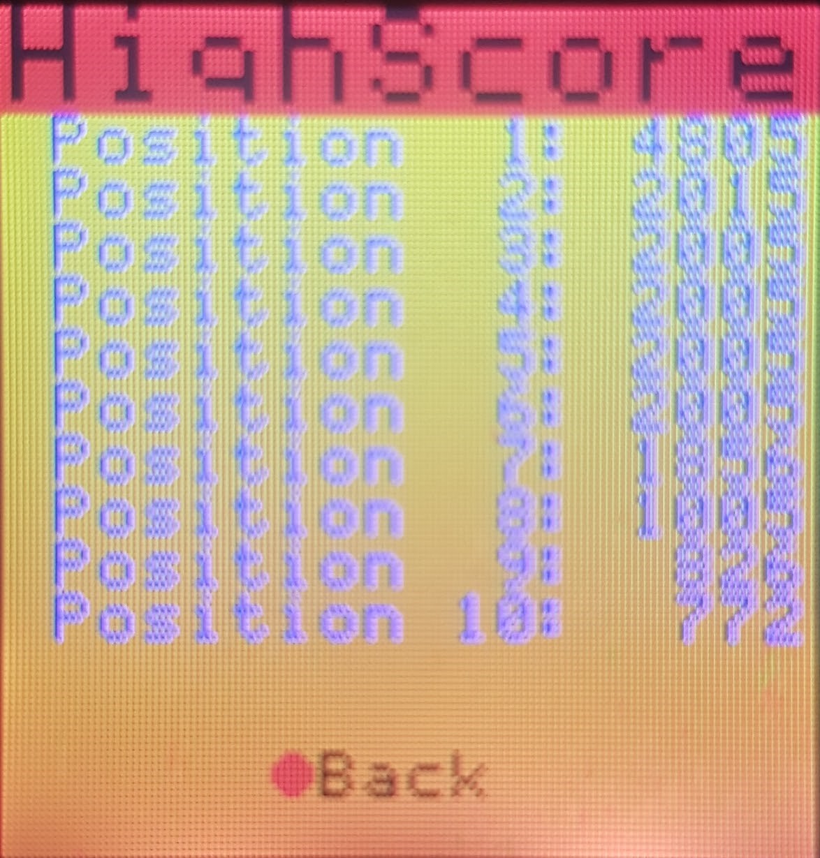
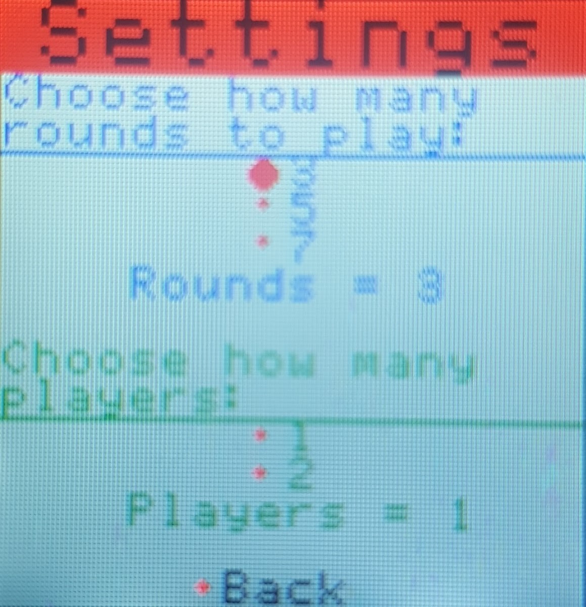
An LCD screen will be used to display a menu for the game. The menu includes a settings option which allows one to change the number of rounds in the game. A high score option is also available which shows the top 10 high scores of the game that are stored on a SD card. Furthermore, the menu can pause and start the game. A nav switch is used to control a blinking cursor which helps in navigating through the menu options. Additionally, a speaker is used to play music while the players are in the menu screen.
A time bar is implemented in the game which shows how much time is remaining for each round. A potentiometer is used to scale the size of the cursor for selecting menu options.
Schematic


Demonstration Video

Image of Player 1 winning

PowerPoint Presentation
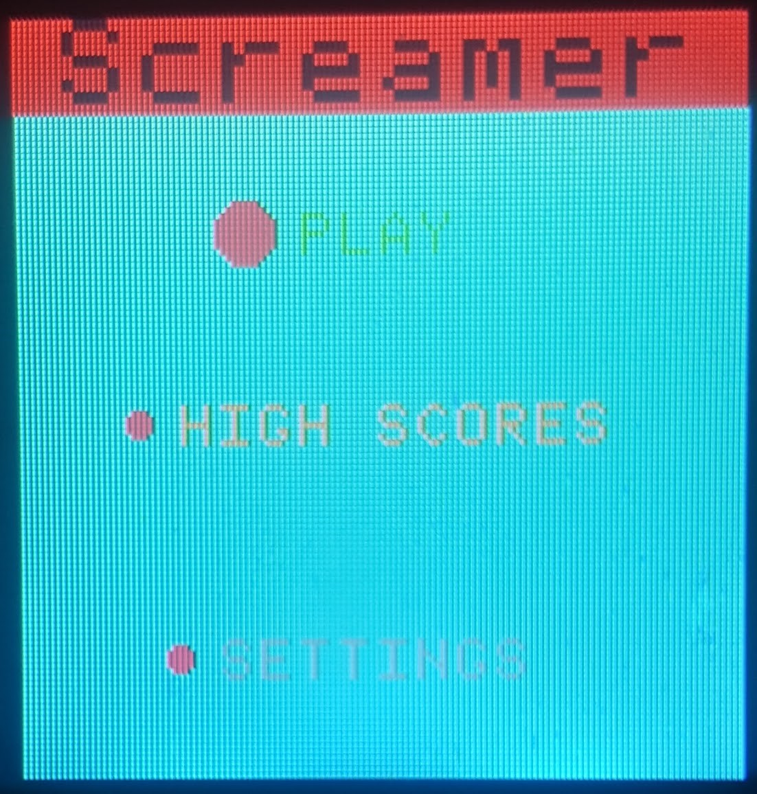
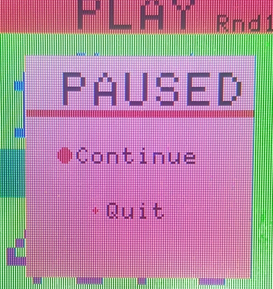
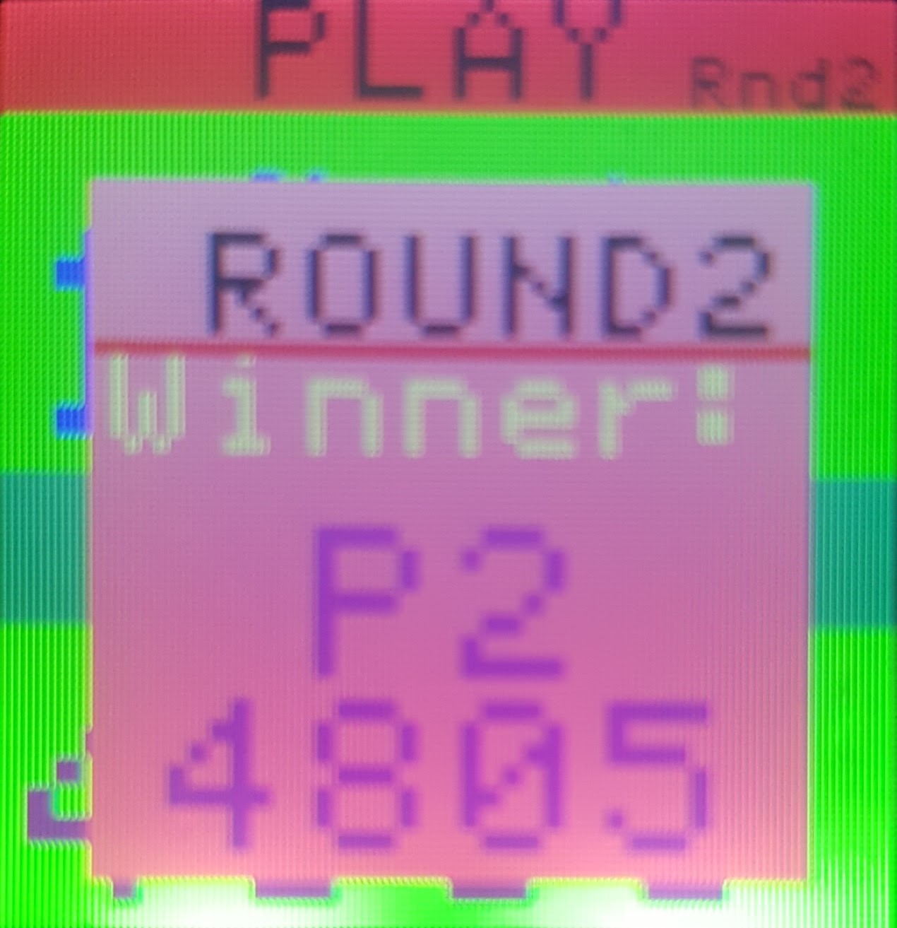
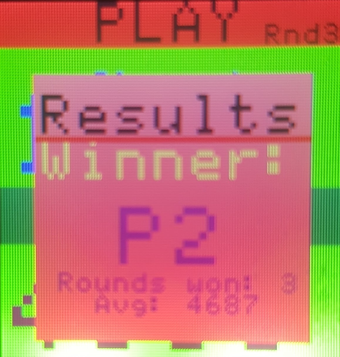
Images of UI
The screens for each state of the game from left to right: Menu, Highscores,Settings,Play,Pause, Results of a Round, and Results of Game
Instructions
Note:The up and down position allows you to move the cursor up and down through the menu options. The middle button allows you to select the option. Note: SD card and microSD card breakout board must be setup or program will not run.
- Follow schematic and build the layout.
- Compile program located on this site and download the file onto the mbed. A menu screen will appear.
- Move the cursor through the menu options by moving the navigation switch’s stick up and down.
- Navigate to the “Play” option and press the nav switch’s middle button to select the option.
- Each player moves close to their respective microphone and yell into their microphone.
- Each player continues to yell into their microphone until the time limit expires or a player causes all the LEDs to turn to the color associated with the player.
- After either condition is fulfilled, a game over screen will appear showing who won. If a high score was achieved, it will be saved to the SD card.
- Navigate pass the game over screen by pressing the middle button of the Nav switch. The menu screen will appear again.
Additional Features: Pause or Quit the Game while playing
- While on the “Play” screen, use the nav switch to navigate to the “Pause” button. Press the nav switch’s middle button to pause the game and display two options.
- Move the cursor to either “Continue” or “Quit” and press the middle button of the nav switch to either resume or quit the game, respectively.
Additional Features: Settings
- On the menu screen, navigate to the “Settings” option.
- Move the cursor and select the number of rounds to be played.
- Exit by navigating to the “Back” option and press the middle button of the Nav Switch.
Additional Features: High Scores
- On the menu screen, navigate to the “High Scores” option.
- The High Scores of the game will be shown.
- Exit by navigating to the “Back” option and pressing the middle button of the Nav Switch.
Additional Features: Single Player or Multiplayer
- On the menu screen, navigate to the “Settings” option.
- Move the cursor below the "Ghoose how many players:" setion.
- Select either option "1" or "2" for single player or multiplayer respectively.
- Exit by navigating to the “Back” option and pressing the middle button of the Nav Switch.
- Change cursor size by turning the potentiometer.
Additional Features: Changing cursor size
- Change cursor size by turning the potentiometer.
Parts Used
uLCD-144-G2

| mbed | uLCD Header | uLCD cable |
|---|---|---|
| 5V=VU | 5V | 5V |
| Gnd | Gnd | Gnd |
| TX=P28 | RX | TX |
| RX=P27 | TX | RX |
| P30 | Reset | Reset |
Speaker and audio amp


| mbed | TPA2005D1 | Speaker |
|---|---|---|
| gnd | pwr- (gnd), in - | |
| p18 (any PWM or D/A) | in + | |
| out + | + | |
| out - | - |
LEDs

| mbed | LED |
|---|---|
| Any PwmOut pin (p21 -p26) | + |
| GND | - |
Microphone

| mbed | microphone | (optional) 10uf decoupling capacitor |
|---|---|---|
| gnd | gnd | - |
| VU (+5VDC) | Vin | + |
| p15 (AnalogIn) | DC |
LED strip (DotStar) and APA


| mbed | LED Strip |
|---|---|
| Vu | +5V |
| P5 (MOSI) | DI |
| P7 (SCK) | CI |
| GND | GND |
Nav Switch

| mbed LPC1768 | Sparkfun Nav Switch Breakout |
|---|---|
| gnd | - |
| p25 | U-up |
| p24 | C-center or fire |
| p23 | L-left |
| p22 | D-down |
| p21 | R-right |
| nc – using internal pullups | + |
MicroSD Breakout Board

| mbed | MicroSD Breakout |
|---|---|
| p10 | CS |
| p11 | DI |
| VOUT | VCC |
| p13 | SCK |
| GND | GND |
| p12 | DO |
| nc | CD |
Potentiometer

| mbed | Potentiometer |
|---|---|
| VOUT | 3.3V |
| p16 | P |
| GND | GND |
Demo Implementation and Code
Please log in to post comments.