HM10 Guide

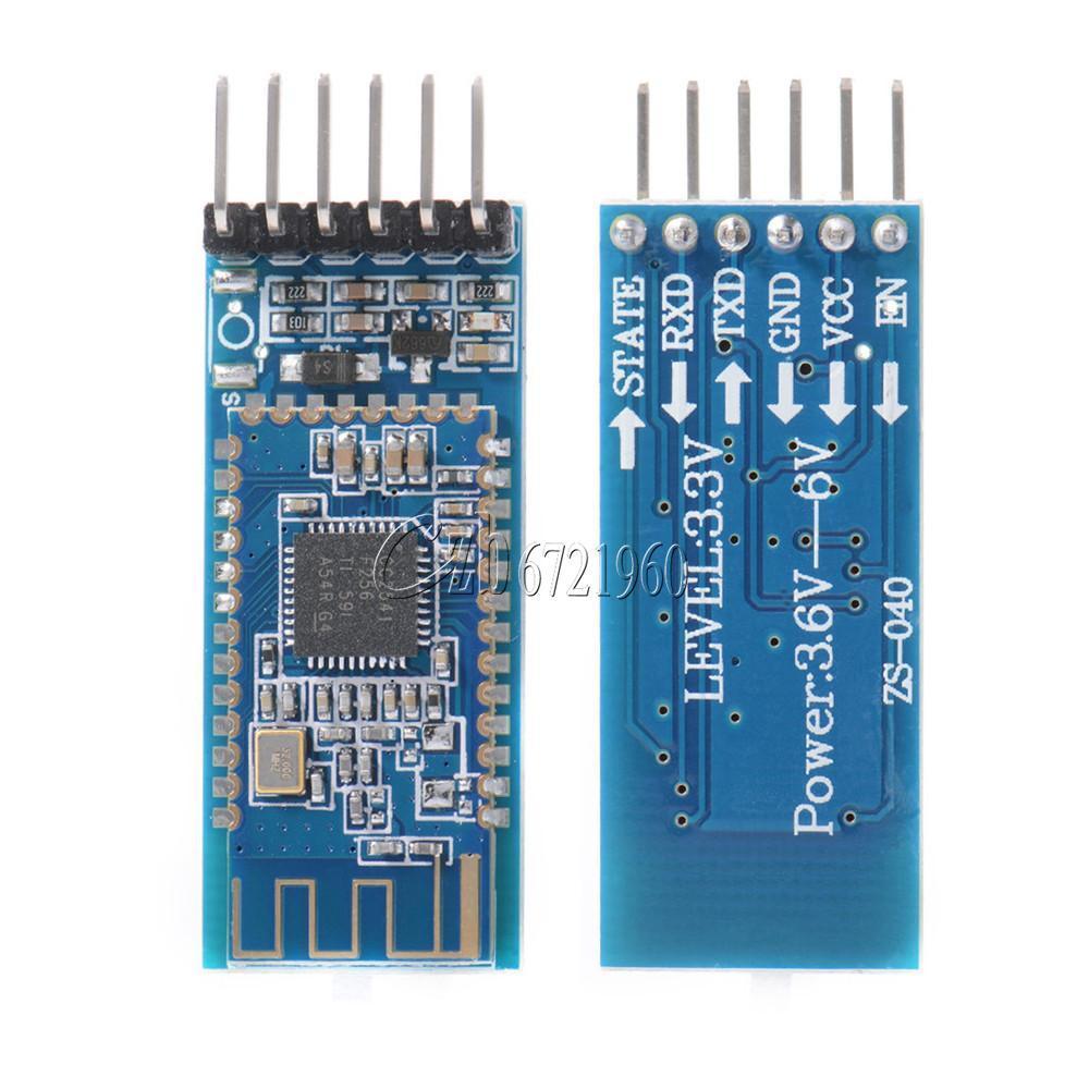
When it comes to Bluetooth, there are a plethora of devices in existence on the market. For our Embedded Systems class, we used the Bluefruit LE module found here. The main problem I have encountered with a device like this is not usability, but cost. Imagine creating a network of several nodes that need to communicate wirelessly. Each node would need one of these transceivers, and $20 per node is not cost effective. Instead, something like the HM10 can be used. At a cost of $3 per breadboard-compatible transceiver, this device is much more suitable for a low-cost project. It is slightly more difficult to use than the Bluefruit, which even has an app to go along with it, but it is just as capable.
The wiring setup for the HM10 is similar to other Bluetooth devices. It connects to Serial on the mbed LPC1768 as follows:
| mbed | HM10 |
|---|---|
| GND | GND |
| VU (or Vout) | VCC |
| p9 (TX) | RXD |
| p10 (RX) | TXD |
HM10 AT Commands Demo
To configure the HM10 and set transmit power, PIN, baud rate, etc., we can use AT commands. Whenever the device is not connected to another device through Bluetooth, a program like the following lets the user send ASCII commands to the HM10 through a bidirectional Serial port (the Arduino IDE has one built in, PuTTY also works).
HM10_Driver
#include "mbed.h"

// set up the HM10 Serial connection
Serial hm10(p9,p10); //TX, RX
Serial pc(USBTX, USBRX);

int main()
{
    //char buf[100];
    //int counter = 0;
    hm10.baud(9600); //make sure the baud rate is 9600
    while (!hm10.writeable()) { } //wait until the HM10 is ready
    hm10.printf("AT+HELP\r\n");
    while(1) {
        if (hm10.readable())
        {
            pc.putc(hm10.getc());
        }
        if (pc.readable())
        {
            hm10.putc(pc.getc());
        }
    }
}
With this, a variety of commands can be used to control and modify the operation of the HM10. The line
hm10.printf("AT+HELP\r\n");
prints out a basic set of AT commands, and more can be found in documentation. For example, AT+BAUD returns the baud rate of the device. The default value of this is 4, which corresponds to a baud rate of 9600. Some commands can take in inputs as well, which directly follow the command: AT+ROLE1 sets the role of the device to master, while AT+ROLE0 sets the role of the device to slave. This last command will be used in the demo when connecting two devices.
HM10 Demo with Two Chips
This demo uses two mbeds and two HM10 chips. One chip acts as the master while the other acts as the slave. The code below shows both the master main.cpp and the slave main.cpp.
master main.cpp
#include "mbed.h"
DigitalOut l1(LED1);
DigitalOut l2(LED2);
DigitalOut l3(LED3);
DigitalOut l4(LED4);

Serial hm10(p9,p10); //TX, RX
Serial pc(USBTX, USBRX);

int main()
{
    //char buf[100];
    //int counter = 0;

    while(!hm10.writeable()) {} //wait until writeable

    pc.printf("\r\nStarting Master Program\r\n");
    hm10.printf("AT+RENEW\r\n");
    pc.printf("Device Reset\r\n");
    wait(2);
    hm10.printf("AT+ROLE1\r\n");
    pc.printf("Device Set to Master\r\n");

    while (hm10.readable()) //flush hm10 buffer
        pc.putc(hm10.getc());

    wait(2);
    hm10.printf("AT+INQ\r\n"); //inquires if there are any slaves nearby
    pc.printf("Device Looking for Slaves\r\n");

    int numDevices = -1;

    while (numDevices <= 0) {
        if (hm10.getc() == 'D') { //waits for "Devices Found x" line
            for (int i = 0; i < 13; i++) //skip to number of devices
                char temp = hm10.getc();

            numDevices = hm10.getc() - '0';
            pc.printf("Found %i Slave Devices \r\n", numDevices);
            if (numDevices == 0)
                hm10.printf("AT+INQ\r\n");
        }
    }
    pc.printf("Connecting to device 1\r\n");
    hm10.printf("AT+CONN1\r\n"); //connects to first device in the list
    wait(3); //wait to connect
    hm10.putc('&'); //send & to test if connection is established
    pc.printf("Sending test character, waiting for ACK\r\n");
    while (hm10.getc() != '&') { hm10.putc('&'); } //wait for acknowledgement

    pc.printf("ACK received\r\n"); //received &, and can proceed with instructions
    pc.printf("Writing LEDs\r\n");
    int ledNum = 1;
    while(1) { //send instructions to slave to turn on LEDs
        while (hm10.readable())
        {
            pc.putc(hm10.getc());
        }
        if (hm10.writeable())
        {
            hm10.printf("!L%i", ledNum);
        }
        ledNum = ledNum % 4 + 1;
        wait(1);
    }
}
slave main.cpp
#include "mbed.h"
DigitalOut led1(LED1);
DigitalOut led2(LED2);
DigitalOut led3(LED3);
DigitalOut led4(LED4);

Serial hm10(p9,p10); //TX, RX
Serial pc(USBTX, USBRX);

int main()
{
    while(!hm10.writeable()) {} //wait until writeable

    pc.printf("\r\nStarting Slave Program\r\n");
    hm10.printf("AT+RENEW\r\n");
    pc.printf("Device Reset\r\n");
    wait(2);
    hm10.printf("AT+ROLE0\r\n"); //set chip to slave mode
    pc.printf("Device Set to Slave\r\n");

    while (hm10.readable()) //flush hm10 buffer (clear characters that have built up)
        pc.putc(hm10.getc());

    wait(2);

    while(hm10.getc() != '&') {} //wait for initialize character from master
    hm10.putc('&'); //send acknowledgement back to the master

    char num = 0;
    while(1) { //turns on LEDs one at a time
        if (hm10.getc()=='!') {
            if (hm10.getc()=='L') {
                num = hm10.getc();
                if (num == '1') {
                    led1 = !led1;
                } else if (num == '2') {
                    led2 = !led2;
                } else if (num == '3') {
                    led3 = !led3;
                } else if (num == '4') {
                    led4 = !led4;
                }
            }
        }

    }
}
In the above code the HM10 chips are connected to the serial ports on the mbed (p9, p10), and the mbed is also connected to the pc. By opening Putty or Tera Term one can view and follow along the example code. The beginning 20 lines sets up the chip and establishes which one is the master and which one is the slave. The master will then look for and inquire if there are any slave chips nearby until the numDevices is greater than 0. Once the master has found a connection to a slave, it will send a ampersand (&) sign to the slave to check the connection. The slave will receive the & sign and send one back if it is connected properly. Once the master has checked the connection, it tells the slave to turn on its four LEDs on the mbed one at a time. The video below shows the demo.
Please log in to post comments.
