Multipurpose Solar Power based Battery Charger
Group Members
- Mihir Rajput
- Swantika Dhundia
- Szilard Liptak
Project Description
The aim of the project is to develop a cheap battery charger that utilizes solar energy to recharge the battery and power any USB compatible loads like a cell phone, a small fan, a light etc. These have numerous advantages over the conventional chargers, the most important one being saving electrical power. Since these chargers are portable, they can be easily carried anywhere and are also environment friendly.
The following tasks were sequentially implemented for design of the solar battery charger:
- Implementation of DC/DC converter with driver circuit- DC/DC buck converter circuit was developed to step down the voltage of the solar panel to a level suitable for battery charging. A PWM signal of desired frequency (f) and duty cycle (d) was fed to a npn transistor from the mbed to drive the p-channel MOSFET. When the MOSFET is on, the diode is reverse biased, and the current flows through the inductor and charges the capacitor for an output voltage. When the MOSFET is off, the current flows through the forward biased diode, inductor and capacitor. The buck converter is therefore, designed to operate in a continuous conduction mode feeding the load at all times.
- Voltage and current sensing- Voltage sensing was implemented using the voltage divider circuits. Three of these were used to sense the input voltage, output voltage and an intermediate voltage. Output current of the DC/DC converter was sensed using a shunt. The sensed values of voltage and currents were further used to implement PID control to adjust the duty cycle of the MOSFET.
- PID control for constant voltage output - The output voltage of the solar panel fed into the DC/DC converter constantly varies during the day. PID controller was used to achieve constant voltage at the output of the DC/DC converter irrespective of the value of the input voltage. Kp, Ki and Kd values were adjusted using trial error method to achieve constant voltage output. The values of Kp, Ki, Kd used in the code are 0.07, 0.1 and 0 respectively. Thus we were able to implement constant voltage charging.
- PID control for constant current output - We implemented a PID controller to maintain constant current output to limit the charging current into the battery. Since our plant didn't change, we used the same values of Kp, Ki and Kd. Thus we were able to implement constant current charging.
- PID control for MPPT - We implemented a very easy and basic idea of MPPT. Whenever the irradiation reduced, the input voltage of the DC/DC converter was maintained using a PID controller. This strategy ensured that we always drew sufficient power from the panel, also avoiding a short circuit.
- Voltage Regulation - Voltage regulator was used to obtain a constant DC voltage (5V) from the output voltage of the buck converter. This voltage level is desired for charging mobile phones etc.
- Data Logging - The input voltage, output voltage and output current values of the DC/DC converter as sensed by the sensors were logged on an SD card using the sparkfun breakout board.
- Charging status indicator- The RGB led was used to indicate the mode in which we are charging the battery. The modes are constant current charging, constant voltage charging and MPPT.
Circuit Diagram
The circuit diagram for the project is shown below.

Physical Circuit
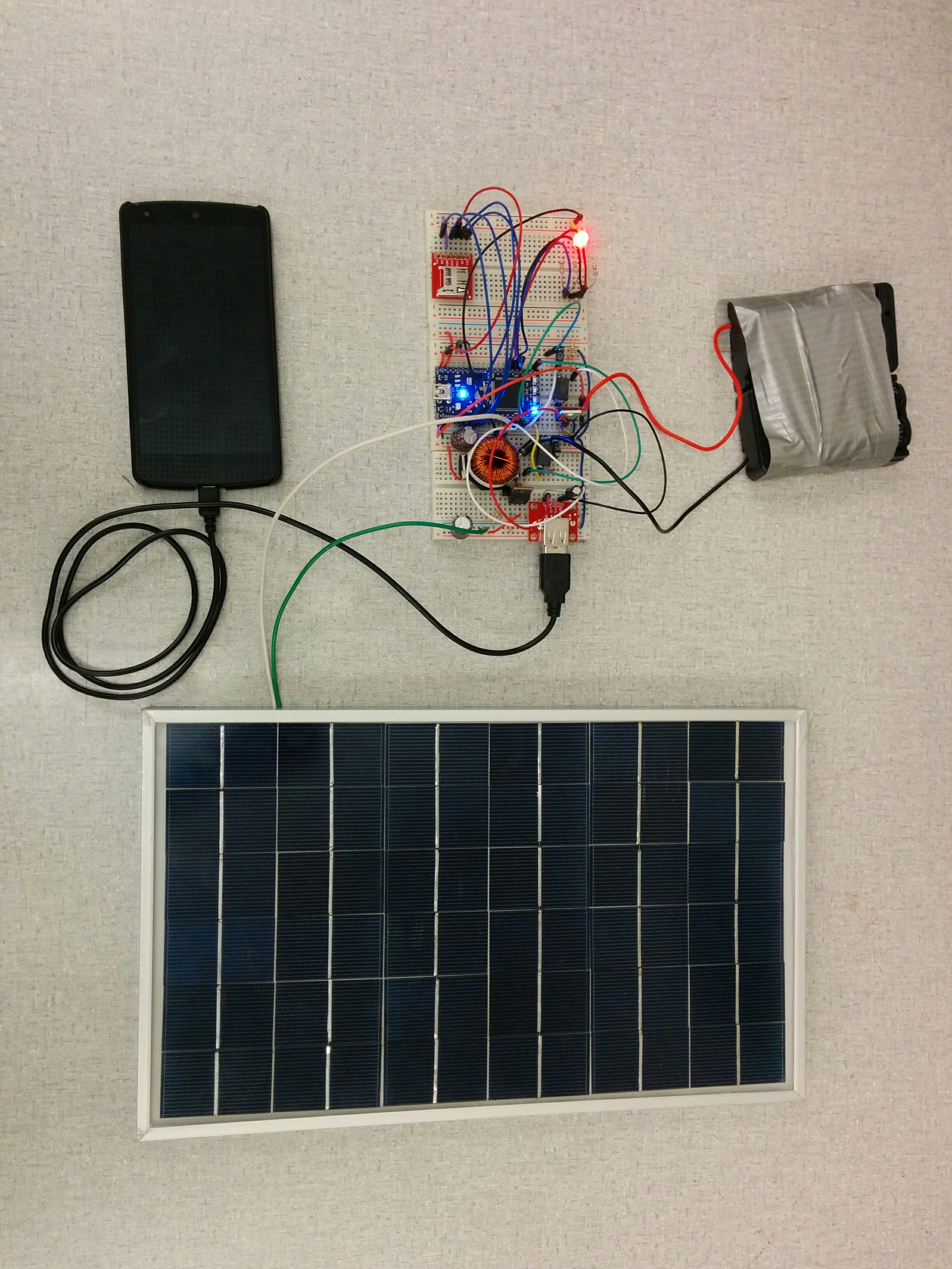
The image of the physical circuit can be seen below.

Sizing of Circuit Components
The ratings of the all circuit components were determined by carrying out appropriate calculations before implementation of the circuit. The following links were referred to for component sizing:
- http://www.ti.com/lit/an/slva477b/slva477b.pdf
- http://www.ti.com/lit/an/slva057/slva057.pdf
- http://www.instructables.com/id/How-to-Size-Your-Off-Grid-Solar-Batteries-1/
Ratings of the Circuit Components
The components with the following ratings were used to build the circuit:
- Resistors - Shown in the circuit diagram
- Capacitors - Shown in the circuit diagram
- Inductors- Shown in the circuit diagram
- Transistor- ST 2N3904 NPN Transistor
- Diode - SR520 schottky diodes
- Solar Panel- 10W, 12V poly-crystalline solar module
- MOSFET- RFP12P08 12A, 80V, 0.3 ohms p-channel MOSFET
- Batteries- 3.7V, 2800mah Rechargeable Li-ion Battery
- Sparkfun USB Breakout Board - https://www.sparkfun.com/products/12700
- Voltage Regulator - LM1085 - 5V, 3A
- RGB LED
- SParkfun SD card Breakout Board - https://www.sparkfun.com/products/544
Mbed Connections
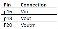
- Voltage and Current Sensing

- Transistor Driver Circuit

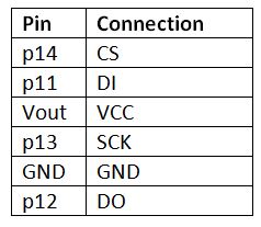
- SD Card Breakout Board

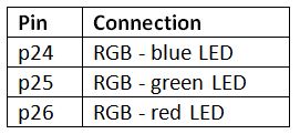
- RGB LED

Project Challenges
- Sizing and designing a buck converter
Circuit Demonstration
Code/Libraries
Robot straight line motion
#include "mbed.h"
#include "mbed.h"
#include "rtos.h"
#include "PID.h"
#include "SDFileSystem.h"

PwmOut red(p26);
PwmOut gre(p25);
PwmOut blu(p24);
PwmOut pwm_out(p21);
PwmOut led(LED1);
AnalogIn bus1(p15), bus2(p18), bus3(p16);   //bus1: 5V, bus2: OutputVoltage (8.6V), bus3: InputVoltage (Vdd):
AnalogIn Voutm(p20);
Serial pc(USBTX, USBRX);
PID Cont(0.07,0.1,0,0.01); //kc,tauI,tauD,Interval
SDFileSystem sd(p11, p12, p13, p14, "sd");

float Bus5V,InputVoltage,OutputVoltage; // global variables for monitoring voltages
float OutputCurrent;  // global variables for monitoring currents
float VoutmAvg, OutputVoltageAvg;
char mode; // mode 1: C and mode 2: V

void SerialReport(void const *args){
    while(true){
        printf("5V Bus = %3.3f     Input V = %3.3f       Output V = %3.3f   Voutm= %3.3f\r\n", Bus5V, InputVoltage, OutputVoltage, Voutm*9.9);
        printf("Output I = %3.3f   Mode = %c  PWM = %3.3f \r\n\n", OutputCurrent,mode, Cont.compute());
        //append sensed values to the file!
        FILE *fp = fopen("/sd/mydir/datalog.txt", "a");
        if(fp == NULL) {
            error("Could not open file for write\n");
        }
        fprintf(fp, "Vin= %f   Vout= %f   Iout= %f\r\n",InputVoltage, OutputVoltage, OutputCurrent);
        fclose(fp);
        Thread::wait(1000);
        led=!led;
        }
    } // thread 1: send data to pc via serial

int main() {
    pwm_out=0;
    led=0;
    int i;
    pwm_out.period_us(200); //5 kHz

    Cont.setInputLimits(0,25);  //
    Cont.setOutputLimits(0,1); //
    Cont.setMode(AUTO_MODE);

    // SD file initialize
    mkdir("/sd/mydir", 0777);

    Thread thread1(SerialReport);

    while (1) {
        //Calculating sensed voltage values from AnalogIn pins
        Bus5V=(bus1*3.3)/0.69;
        OutputVoltage=(bus2*3.3)*3;
        InputVoltage=(bus3*3.3)/0.108;

        VoutmAvg=0;
        OutputVoltageAvg=0;
        for (i=1; i<50; i++) {
            VoutmAvg+=Voutm;
            OutputVoltageAvg+=OutputVoltage;
            wait(0.00002);
        }
        OutputCurrent = (VoutmAvg/50*9.9-OutputVoltageAvg/50)/0.5;


        if ((OutputVoltage<8.4 || OutputCurrent>1) && InputVoltage>16) {    //Do constant current charging!
            Cont.setSetPoint(0.8); //charging current
            Cont.setProcessValue(OutputCurrent);  //current process variable now
            pwm_out=Cont.compute();
            mode='C';
            gre=1;
            red=blu=0;
        }

        if (OutputVoltage>8.4 && OutputCurrent<1 && InputVoltage>16) { //Constant Voltage Charging
            Cont.setSetPoint(8.6); //charging voltage
            Cont.setProcessValue(OutputVoltage);  //voltage process variable now
            pwm_out=Cont.compute();
            mode='V';
            blu=1;
            red=gre=0;
        }

        if (InputVoltage<16) { //Panel Short Protection
            Cont.setSetPoint(14); //panel voltage
            Cont.setProcessValue(InputVoltage);  //voltage process variable now
            pwm_out=1-Cont.compute();
            mode='P';
            red=1;
            blu=gre=0;
        }

        wait(0.02);
    }
}
Please log in to post comments.
