Yet another implementation of wave function generator
A function generator implemented using DAC of KL25Z on FRDM-KL25Z
On 13-Dec-2015 Support for FRDM-K64F added.
Kinetis の DAC を使用したファンクションジェネレータ(以下funcgen)です。
13-Dec-2015 FRDM-K64F のサポートも追加しました。
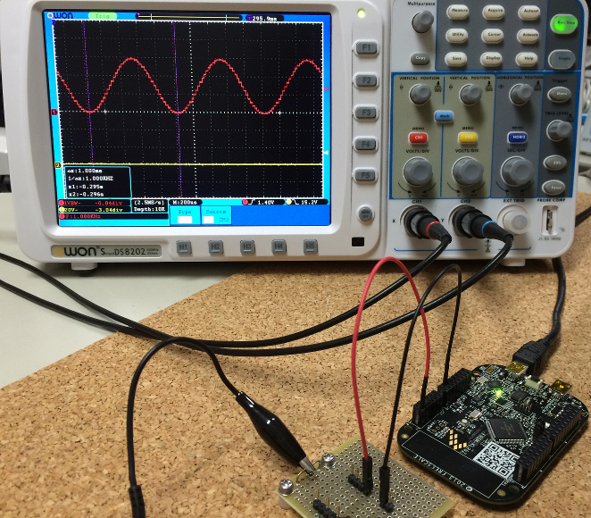
Generates a 1KHz sin wave of 3.0V (p-p) when started.
The analog signal output is analogOut (PTE30), for the GND I was using GND of J2.
起動直後には 1KHz 3V(p-p) のサイン波を生成しています。
アナログ信号は PTE30 から、 GNDについては、J2 の GNDを使用しています。
This funcgen can generate multiple sin, saw, sqr, tri waves in different freq, amp simultaneously.
All the waves are summed to form the output.
この funcgen では 複数の異なる周期、振幅の正弦波、のこぎり波、矩形波、三角波を同時に生成することが可能です。
生成された波形はすべて加算される形で出力波形となります。
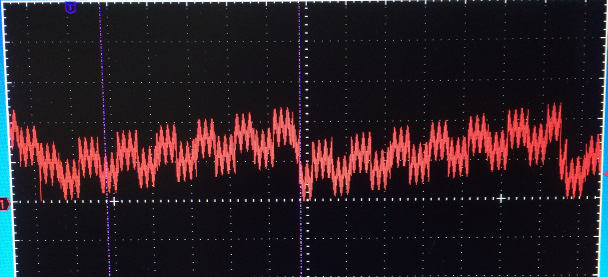
For example following wave form was generated with
sin amp = 0.5V freq = 1000 Hz
sin amp = 0.5V freq = 123 Hz
sqr amp = 0.5V freq = 20 Hz
saw amp = 1.0V freq = 3Hz
たとえば下図の波形は
サイン波 0.5V 1000Hz
サイン波 0.5V 123 Hz
矩形波 0.5V 20Hz
のこぎり波 1.0V 3Hz
を合成して得られたものです。
Some tutorial (簡単な使い方)
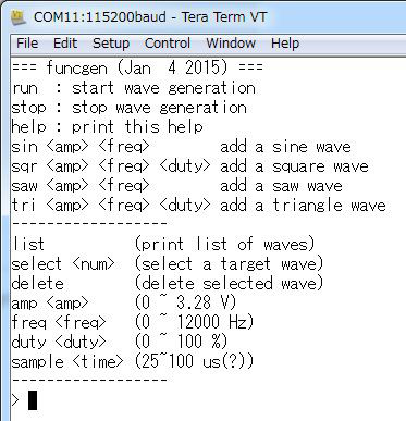
When you connect a terminal program with 115200 baud, 8bit, no parity,
after reset command menu will be presented.
You may also want to enable local echo, so that you can see what you are typing.
ターミナルプログラムで 115200 baud 8bit ノーパリティで接続していると、
リセット後に下記のようなコマンドメニューが表示されます。
入力している文字が表示されるように Local Echo を有効にしておきます。
If you type "list" to the prompt, list of current wave(s) will be shown.
プロンプトに list と入力すると、現在の波形リストが表示されます。

So we can tell that 1 wave of sine whose amplitude is 3.0V
and Frequency is 1000Hz is currently running.
Please ignore duty for sin and saw waves ;-)
The "*" letter in the left shows that this signal is currently selected for operation.
これから、1KHz 3V(p-p)の正弦波が生成されていることがわかります。
デューティー比も表示されていますが、正弦波(sin)とのごきり波(saw)に関しては、
これは無視してください。
また、左側についている“*”マークが、現在この信号がコマンドの対象になっていることを示しています。
At this time the wave form would look like
この時点で波形は下記のようになっています
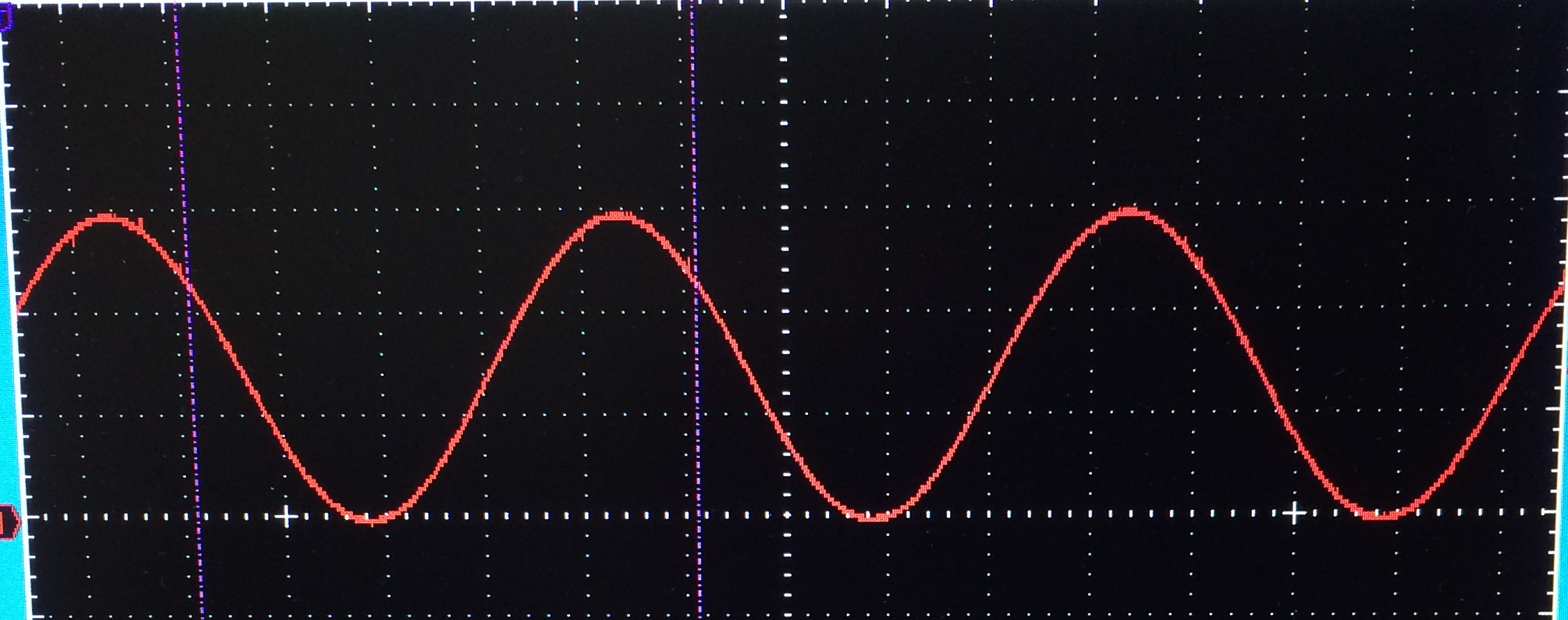
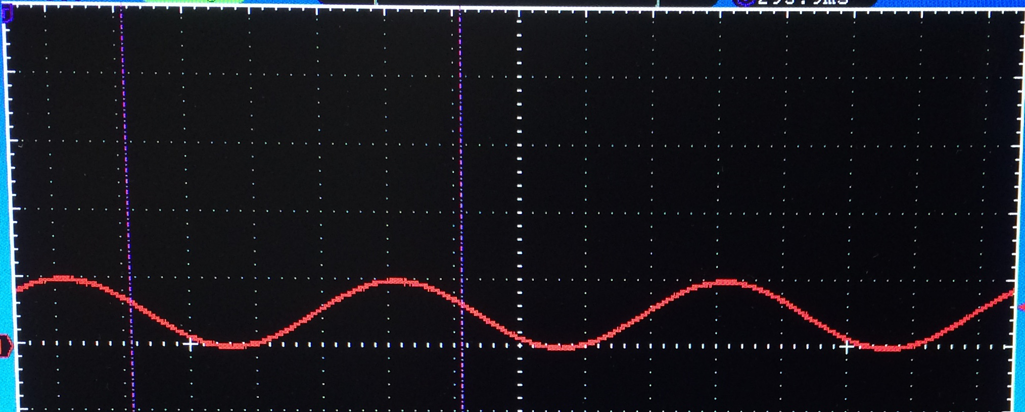
If you type "amp 1" the wave form will be
ここで amp 1 と入力すると波形は下記のようになります
Next let's play with a square wave!
To remove current wave type "delete", then type "sqr 3 1000 50"
which means first delete the sin wave then add a square wave of 3V, 1KHz and duty 50%.
それでは矩形波で遊んでみましょう!
まず正弦波を消すのに“delete”とタイプして、次に“sqr 3 1000 50” とタイプしてください。
これは3V 1KHz デューティ50%の正弦波の追加することになります。

The wave form of Oscilloscope will be something like
オシロの波形は下記のような感じになります
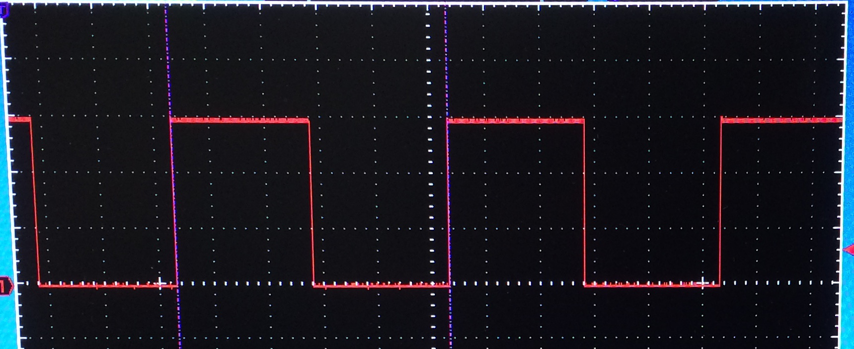
Now if you type "duty 0" you will get
ここで “duty 0” と入力すると
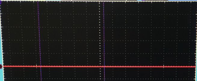
For "duty 20" you will get
“duty 20”では
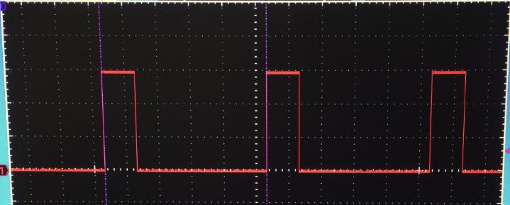
For "duty 80" you will get
"duty 80" では
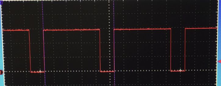
And finally if you specify "duty 100", you will get
最後に“duty 100”を指定すると
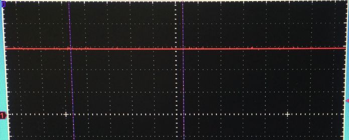
This way, you can also get DC bias of this sqr wave's amplitude.
この方法で、この矩形波の振幅に等しいDC入力とすることもできます。
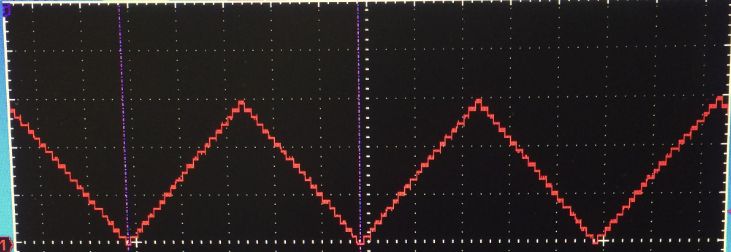
Next, let's try "tri wave", again type "delete" and "tri 3 1000 50", you will get
次に三角波行ってみましょう、再び“delete”、“tri 3 1000 50”と入力しますと
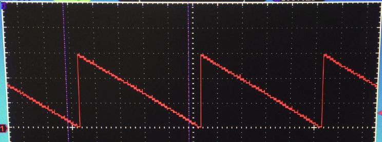
Again if we try, "duty 0", we will get
“duty 0”とすると
For "duty 20"
"duty 20" では
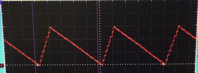
For "duty 80"
"duty 80" では
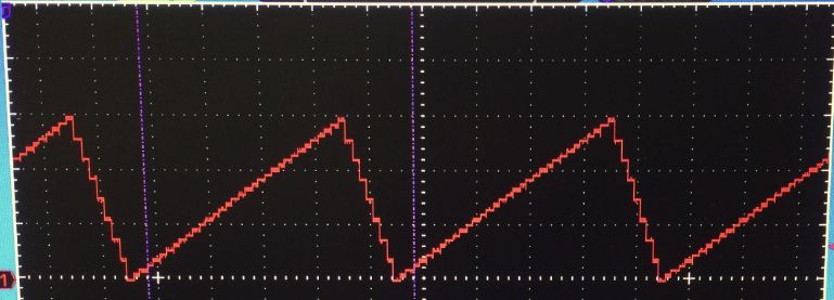
And finally "duty 100"
最後に "duty 100"
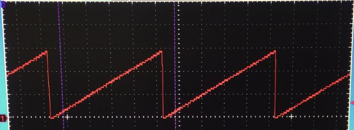
Please note that for the "duty 100",
the triangle wave is identical with "saw" wave,
which I noticed after implementing both of them orz
“duty 100”の三角波はのこぎり波と同じものになります。
気が付いたのは両方の波形をプログラムしちゃってからでした・・・ orz
Multiple waves sample 複数波形の合成例
Now let's try multiple wave composition!
それでは複数波形の合成を試してみましょう!
First let's delete the previous wave, by "delete"
最初に先の信号を"delete" で消しておきます。
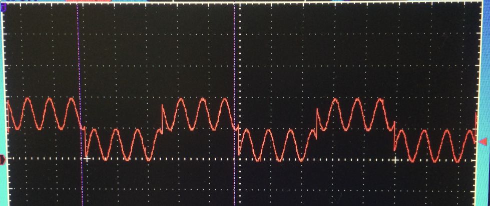
Then type, "sqr 1 100 50", "sin 1 700", you will get
次に "sqr 1 100 50", "sin 1 700" とすると

And adding a saw wave by "saw 1 10" will give us
最後にのこぎり波を "saw 1 10" で追加すると
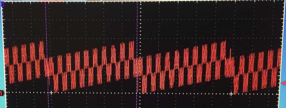
If we enter "list" command we will see
ここで list コマンドを入力すると

Note the "*" letter specify the selected wave,
so if you enter "amp", "freq", "duty", "delete" command,
it will be applied to this wave.
If you want to manipulate other wave,
use "select #" command to specify the wave you'd like to modify.
For example, if you enter "select 0" then the sqr wave at No.0 will be selected.
左側の"*"マークが現在選択されている波形を示しています、
現在"amp", "freq", "duty", "delete" などのコマンドを入力した場合、
その操作はこの波形に対して行われます。
他の波形をモディファイしたい場合には"select #" コマンドを使用してその波形を選択してください。
たとえば "select 0" と入力すると 矩形波(sqr)が選択されることになります。
Revision 1:b4f26ccaf417, committed 2015-12-13
- Comitter:
- Rhyme
- Date:
- Sun Dec 13 07:27:43 2015 +0000
- Parent:
- 0:46a79748aa81
- Commit message:
- Support for FRDM-K64F added;
Changed in this revision
| main.cpp | Show annotated file Show diff for this revision Revisions of this file |
| vt100.lib | Show annotated file Show diff for this revision Revisions of this file |
diff -r 46a79748aa81 -r b4f26ccaf417 main.cpp
--- a/main.cpp	Sun Jan 04 10:21:07 2015 +0000
+++ b/main.cpp	Sun Dec 13 07:27:43 2015 +0000
@@ -14,6 +14,100 @@
 #include "math.h"
 #include "vt100.h"

+#if defined (TARGET_KL25Z)
+#define PIN_SCLK        PTD1
+#define PIN_MISO        PTD3
+#define PIN_MOSI        PTD2
+#define PIN_CS_TFT      PTD0
+#define PIN_DC_TFT      PTD5
+#define PIN_CS_TSC      PTA13
+#define PIN_BL_TFT      PTC9
+#define PIN_CS_SD       PTA4
+#define PIN_TSC_INTR    PTC6 /* place holder */
+#define PIN_RESET_TFT   PTC5 /* place holder */
+#define PIN_ADC_CH0     PTB0
+#define PIN_ADC_CH1     PTB2
+#define PIN_DAC_OUT     PTE30
+
+#elif defined (TARGET_KL46Z)
+#define PIN_SCLK        PTD5
+#define PIN_MISO        PTD7
+#define PIN_MOSI        PTD6
+#define PIN_CS_TFT      PTD4
+#define PIN_DC_TFT      PTD2
+#define PIN_CS_TSC      PTA13
+#define PIN_BL_TFT      PTC9
+#define PIN_CS_SD       PTA4
+#define PIN_TSC_INTR    PTC7 /* place holder */
+#define PIN_RESET_TFT   PTC6 /* place holder */
+#define PIN_ADC_CH0     PTB0
+#define PIN_ADC_CH1     PTB2
+#define PIN_DAC_OUT     PTE30
+
+#elif defined (TARGET_K64F)
+#define PIN_SCLK        PTD1
+#define PIN_MISO        PTD3
+#define PIN_MOSI        PTD2
+#define PIN_CS_TFT      PTD0
+#define PIN_DC_TFT      PTC4
+// for board rev E or later
+#define PIN_CS_TSC      PTC12
+// for earlier boards use following line
+// #define PIN_CS_TSC      PTA0
+#define PIN_BL_TFT      PTC3
+#define PIN_CS_SD       PTB23
+#define PIN_TSC_INTR    PTC0 /* place holder */
+#define PIN_RESET_TFT   PTC9 /* place holder */
+#define PIN_ADC_CH0     PTB2
+#define PIN_ADC_CH1     PTB10
+#define PIN_DAC_OUT     DAC0_OUT
+
+#elif defined (TARGET_K22F)
+#define PIN_SCLK        PTD5
+#define PIN_MISO        PTD7
+#define PIN_MOSI        PTD6
+#define PIN_CS_TFT      PTD4
+#define PIN_DC_TFT      PTA1
+#define PIN_CS_TSC      PTB19
+#define PIN_BL_TFT      PTC6
+#define PIN_CS_SD       PTA4
+#define PIN_TSC_INTR    PTC7 /* place holder */
+#define PIN_RESET_TFT   PTC9 /* place holder */
+#define PIN_ADC_CH0     PTB0
+#define PIN_ADC_CH1     PTC1
+#define PIN_DAC_OUT     DAC0_OUT
+
+#elif defined (TARGET_NUCLEO_F411RE)
+#define PIN_SCLK        PA_5
+#define PIN_MISO        PA_6
+#define PIN_MOSI        PA_7
+#define PIN_CS_TFT      PB_6
+#define PIN_DC_TFT      PC_7
+#define PIN_CS_TSC      PA_9
+#define PIN_BL_TFT      PA_8
+#define PIN_CS_SD       PB_5
+#define PIN_TSC_INTR    PA_8 /* place holder */
+#define PIN_RESET_TFT   PA_13 /* place holder */
+#define PIN_ADC_CH0     PA_0
+#define PIN_ADC_CH1     PA_4
+
+#else
+ #error TARGET NOT DEFINED
+#define PIN_SCLK        D13
+#define PIN_MISO        D12
+#define PIN_MOSI        D11
+#define PIN_CS_TFT      D10
+#define PIN_DC_TFT      D9
+#define PIN_CS_TSC      D8
+#define PIN_BL_TFT      D7
+#define PIN_CS_SD       D4
+#define PIN_TSC_INTR    NC
+#define PIN_RESET_TFT   NC
+#define PIN_ADC_CH0     A0
+#define PIN_ADC_CH1     A2
+
+#endif
+
 #include "wave.h"
 #include "sinwave.h"
 #include "sqrwave.h"
@@ -25,8 +119,10 @@

 #define MAX_WAVE 10

-DigitalOut myled(PTB18) ;
-AnalogOut aout(PTE30) ; // SignalOut
+
+
+DigitalOut myled(LED1) ;
+AnalogOut aout(PIN_DAC_OUT) ; // SignalOut

 Ticker *timer ;
 wave *wave_list[MAX_WAVE] ;
diff -r 46a79748aa81 -r b4f26ccaf417 vt100.lib
--- a/vt100.lib	Sun Jan 04 10:21:07 2015 +0000
+++ b/vt100.lib	Sun Dec 13 07:27:43 2015 +0000
@@ -1,1 +1,1 @@
-http://developer.mbed.org/users/Rhyme/code/vt100/#94253645a02a
+http://developer.mbed.org/users/Rhyme/code/vt100/#b7229a9eae1c