Mini-Mouse

The Mini-Mouse is small robot that should be able to solve IEEE micromouse mazes. I'm not aiming for the 5 second solutions that the "professionals" can achieve but It'd be nice to be fairly speedy.
The Specification
The aim is to construct a mouse that can:
- Move through a typical IEEE micro mouse maze
- Do so with sufficient accuracy
- Sense the walls such that a map can be made
- With an end goal of solving the maze inside of a minute
This list of requirements would typically suggest the use of DC motors attached to quadrature encoders. This then forms a closed loop control system allowing fine control of the motors hopefully leading to accurate movements in the maze. However the quadrature encoders only look at the output of the motors, they do not measure any slipping of the wheels.
To counteract this I though that an optical mouse sensor would be ideal. These sensors are specifically designed to accurately track the movement of a device on a surface. This is a pretty similar use case to micro mice.
Parts List
An mBed

I will need some way of controlling the mouse. This will involve reading the IR wall sensors, the optical mouse sensor, controlling the motors and running the mapping algorithm. As I was unsure of the requirements of the optical mouse sensor I decided to use the most powerful development board I could find.
TB6612FNG Breakout Board

I received this as part of a Sparkfun Freeday as I was quite keen to try it out despite the TB6612FNG chip not being available here in the UK. It is a 2 channel, 1.2Amp constant, 3.2 Amp peak DC motor driver. Each channel has 2 pins to control the H-bridge and a PWM pin for speed control. There is also a global enable pin which allows you to disable the motors saving power.
PAW3102DB Optical Mouse Sensor

This optical mouse sensor was "rescued" from a cheap optical mouse bought for £3.99. It had a PS/2 connector as I figured that would be the easiest thing to reverse engineer. When it was opened up I could that there were two chips inside, one that interfaced with the PS/2 connector and the PAW3102DB sensor. After much googling eventually a datasheet for the PAW3102DB was found.
2 motors, wheels, and motor brackets


Needing some way to move the mouse I bought these. The motors are "50:1 Micro Metal Gearmotor HP", the wheels are "Pololu Wheel 32x7mm Pair - Black" and the holders are "Pololu Micro Metal Gearmotor Bracket Pair - Black".
Warning!
I've found that over time the plastic brackets actually develop cracks and eventually break. They still seem to work, but despite super gluing them back together they've only cracked again. I may try and replace these at some point in the future.
3/8" Ball Caster

Using the remains of the optical mouse sensor for the rear caster I needed a caster at the front to stop the mouse from excessive rocking when it stopped. I bought a "Pololu Ball Caster with 3/8" Plastic Ball" which fit really nicely on the front and worked really well.
4 pairs of IR LEDs & Phototransistors


To "see" the walls, and, ideally, get positioning data from them I need sensors that have a range of approximately 180mm. To achieve this I'm going to use the standard solution of an Infra Red (IR) LED and an IR phototransistor. These two components are mounted such that the presence of a wall reflects the LEDs IR light back to the phototransistor that produces a voltage that is read by the mBed's ADC.
I'm currently using the SFH4550 IR LED which has a 5° spread and the BPW77NA phototransistor that also has a 5° spread. These very narrow spreads should result in great accuracy as the phototransistor will ignore IR light that is greater than 5° off axis.
Buzzer

Added to give a little audio feedback as the mouse navigates the maze. This is because the rules won't allow any remote interfaces with the mouse while it's in the maze.
SPST switch

This is the on/off switch, very handy!
Microswitch

This is the "run" switch. Pressing this gives the mouse the instruction to begin the maze solving.
Battery holder for 4 AAs

The mouse needs to have a power source. 4 AA batteries with 1.2Volts & 2000mAh should last long enough whilst not being too heavy. Ideally these will be replaces with a lithium battery pack at some point.
General components
These are the common resistors and capacitors found in circuits. Need to have decoupling on the different chips to ensure error free operation. Need to bias the IR LEDs as well as connect to the batteries to monitor voltage.
Build Pictures
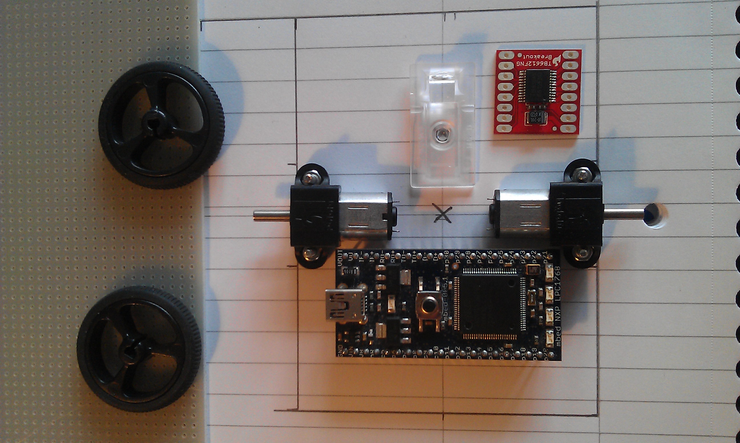
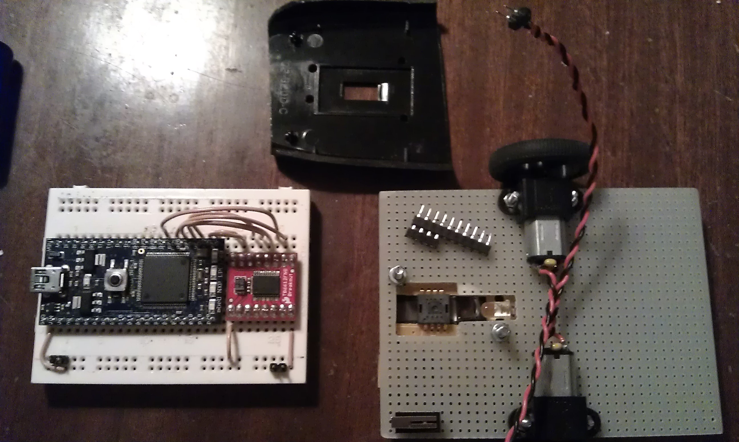

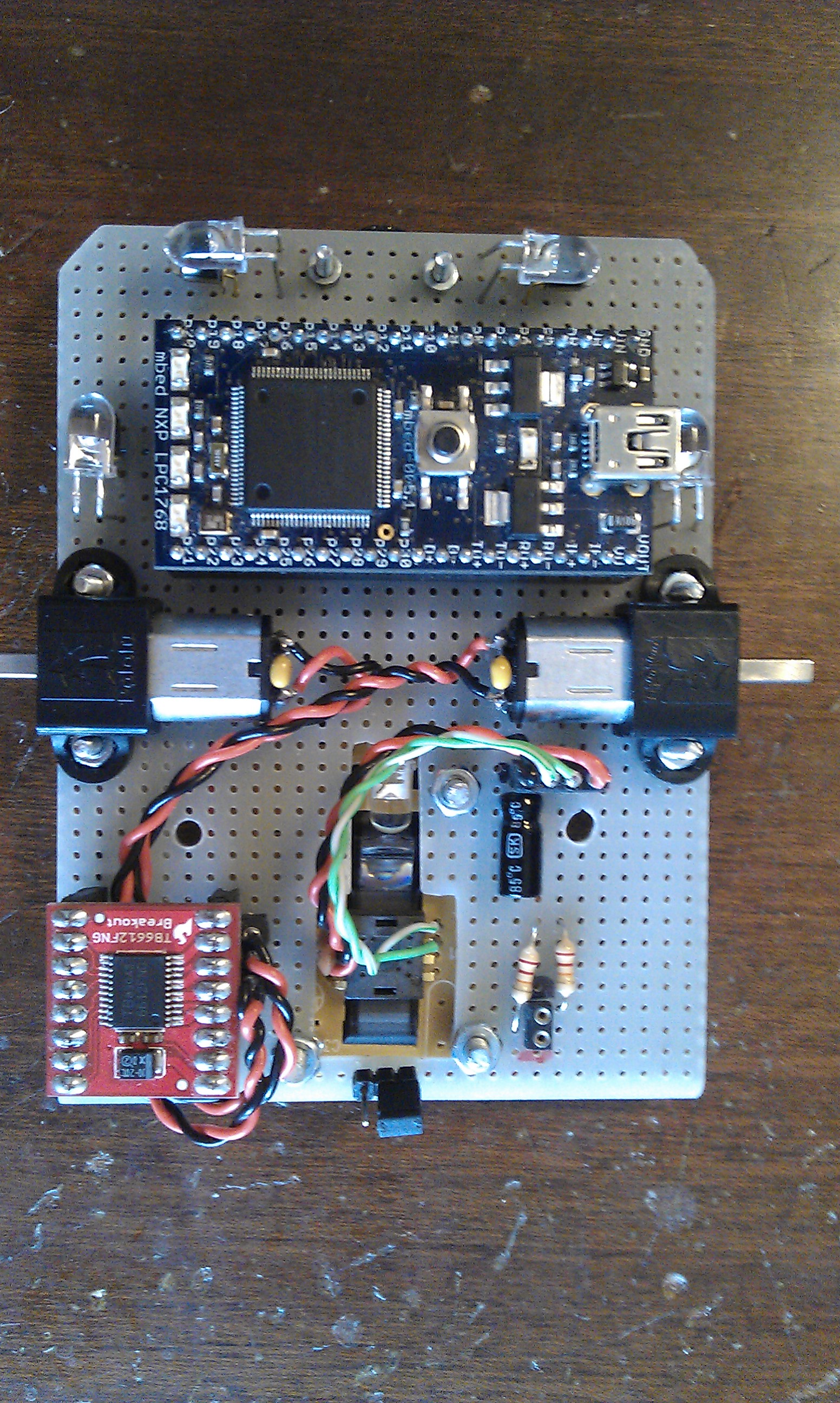
I started designing my mouse by laying the parts out on a rough drawing of the chassis. This helped me to see where the parts could be placed and how much space I had to spare. I then tried to get the motor driver working with the mBed on breadboard, primarily to ensure that it worked before I soldered things into their final positions. In parallel with this I also started morning the motors and the optical mouse sensor on the chassis. Once I was happy with the positions of things I started to solder the headers for the motor driver and mBed into place. I also added the support circuitry for the optical sensor and wall sensors.
Later on I also added a buzzer and transistor for the LEDs under the mBed as there was some remaining space there.
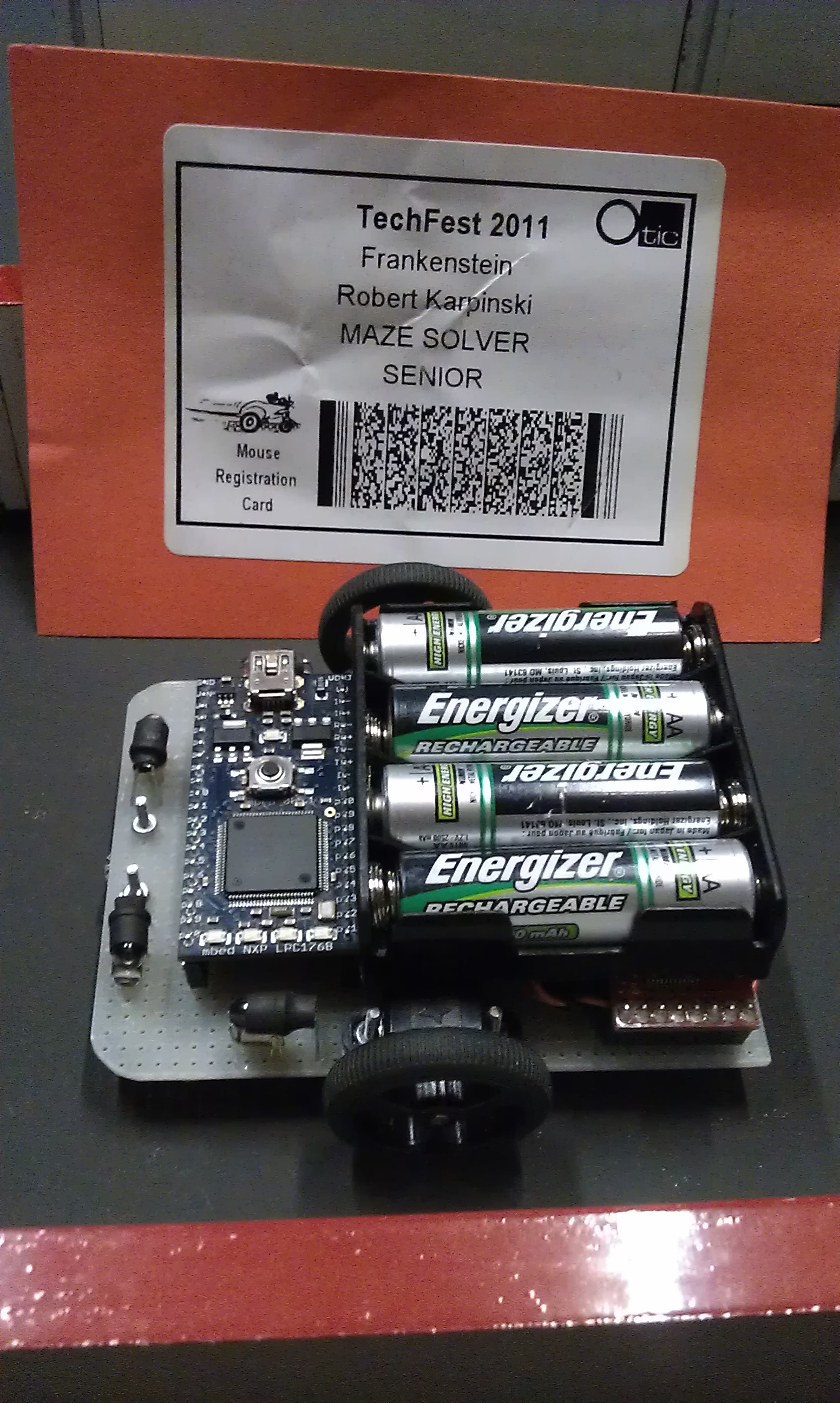
The Finished Mouse
The Code
The mouse needs some firmware written so that it can move but more importantly navigate through the maze.
Results
- Very hard to correctly deal with the mouse sensor as a control system.
- Capable of going VERY fast, but leads to more errors.
- IR wall sensors are very difficult to setup
The Competitions
- Techfest - Birmingham - 2011: not placed
- Techfest - Birmingham - 2012: We'll see...
1 comment on Mini-Mouse:
Please log in to post comments.
Hello, please guide me on setting up the PAW3102DB sensor on Telegram to Dexxxter_gg or on Instagram to dexter85gg.