4180Balancer
 Austin Lowe.
1 reply
Austin Lowe.
1 reply
Created by John Lee, Nyle Malik, and Austin Lowe
Import program4180Balancer
Balances a robot on two wheels using a PID controller for fine tuning the motor speed and behavior. It uses an IMU to send input to the PID controller and calibrate the robot's desired angle.
Last commit 06 Dec 2019 by John Lee
Project Idea
The general idea of this project was to design a movable robot with a tall base that adjusts its wheel speeds to stay upright. With major changes in parts used, complexity of design, and how the motors are driven, it was inspired by Mark William's Success with a Balancing Robot using a Raspberry Pi. Our design incorporated learnings and parts from previous labs within 4180 itself, such as the use of a dual H bridge motor driver, IMU, and the Mbed, as well as new concepts developed in Mark William's project, including work with a PID controller and encoders. The combination of these efforts led to what we call the 4180Balancer.
PID Explained
One of the main difficulties of this project was dealing with PID, Proportional Integral Derivative. PID is a control algorithm that keeps the robot stable and balanced by ensuring that the center of gravity is always inline, above the wheels. The main features in our PID are acceleration and gyro, measured by the IMU as it moves around.
First, the gyro should determine the speed of rotation in degrees per second. This number will be found by multiplying by a constant value depending on the sensitivity of a particular gyro by the raw data from the x-axis. Once this speed of rotation is found, multiply it by the time it takes to complete one cycle of the main loop, and save this number as propAngle, the current X angle determined by the gyro.
Next, we can compute the accelerometer angle by taking the raw accelerometer Y and Z values and using *Atan2* to determine the X angle. This number should be added to pi and then converted from radians to degrees. As a result, save this value as the aAngle, the acceleration of the X angle.
Finally, we need to add our filter. Two main ones you could use are the Kalman Filter or the Complementary Filter, but we went with the Complementary Filter because it is simpler to understand and less harsh on your CPU. With our resulting degrees from the previous part, run the following equation to get a final angle that will be used to balance the 4180Balancer.
propAngle = FILTER_CONSTANT * (propAngle + gAngle) + (1 - FILTER_CONSTANT) * aAngle - angle
Demo of 4180Balancer
Instructions
Prior knowledge of the following concepts were used:
- Controls
- C++
- Mbed
1. To begin, acquire the following components and materials:
- 9DoF IMU
- Mbed
- Dual H Bridge
- 2 Motors with Encoders
- 2 Wheels
- Mounting Hubs for the Wheels
- 5V Power Cord
- 2 small breadboards
- A 3D-printed base (could be substituted with any other materials, including wood, metal, etc.)
- Super glue
- Zip ties
- Wires
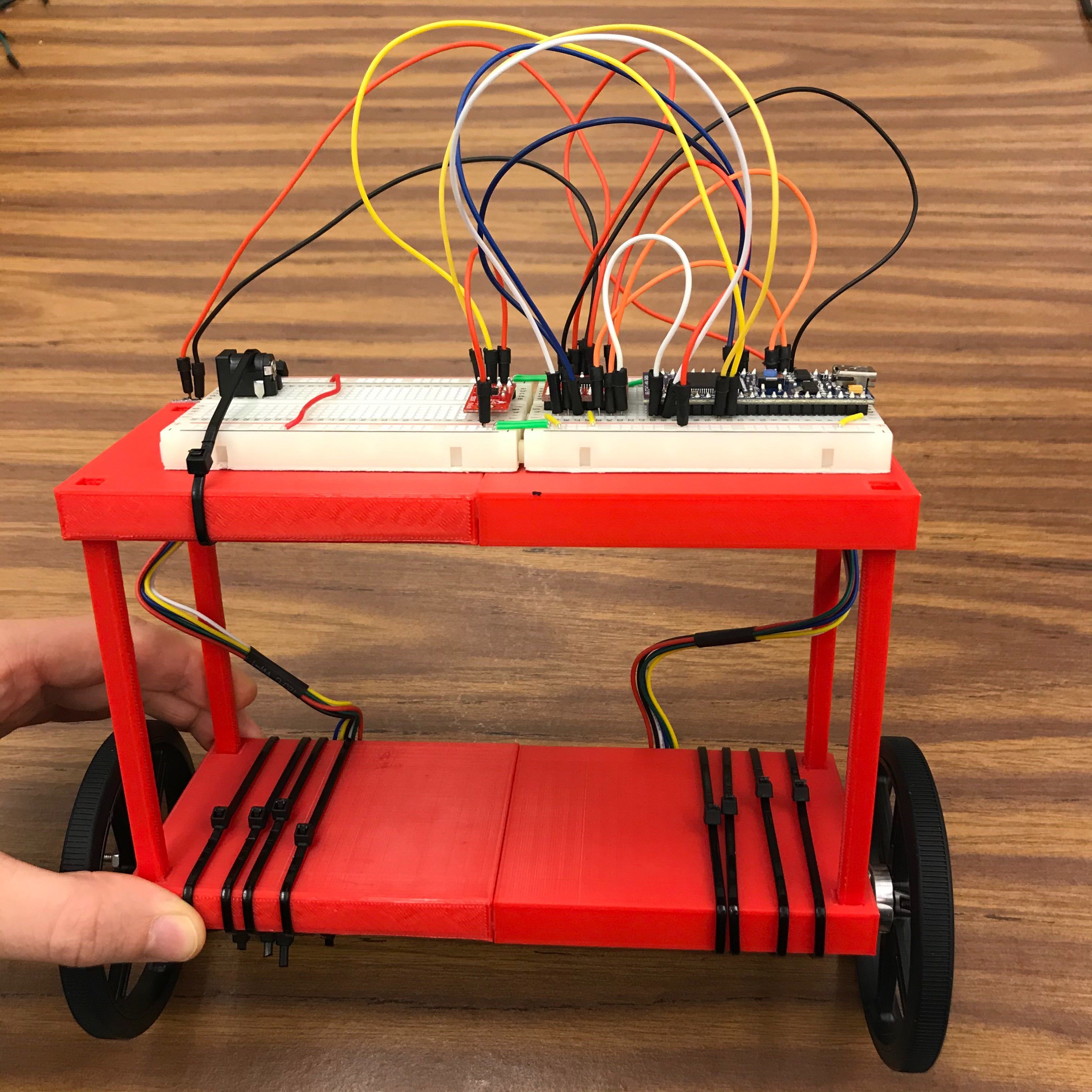
2. Assemble the base whether by 3D printing or building one. Our base was two 8in x 3in x 1/2in parts connected by four 4in rods.
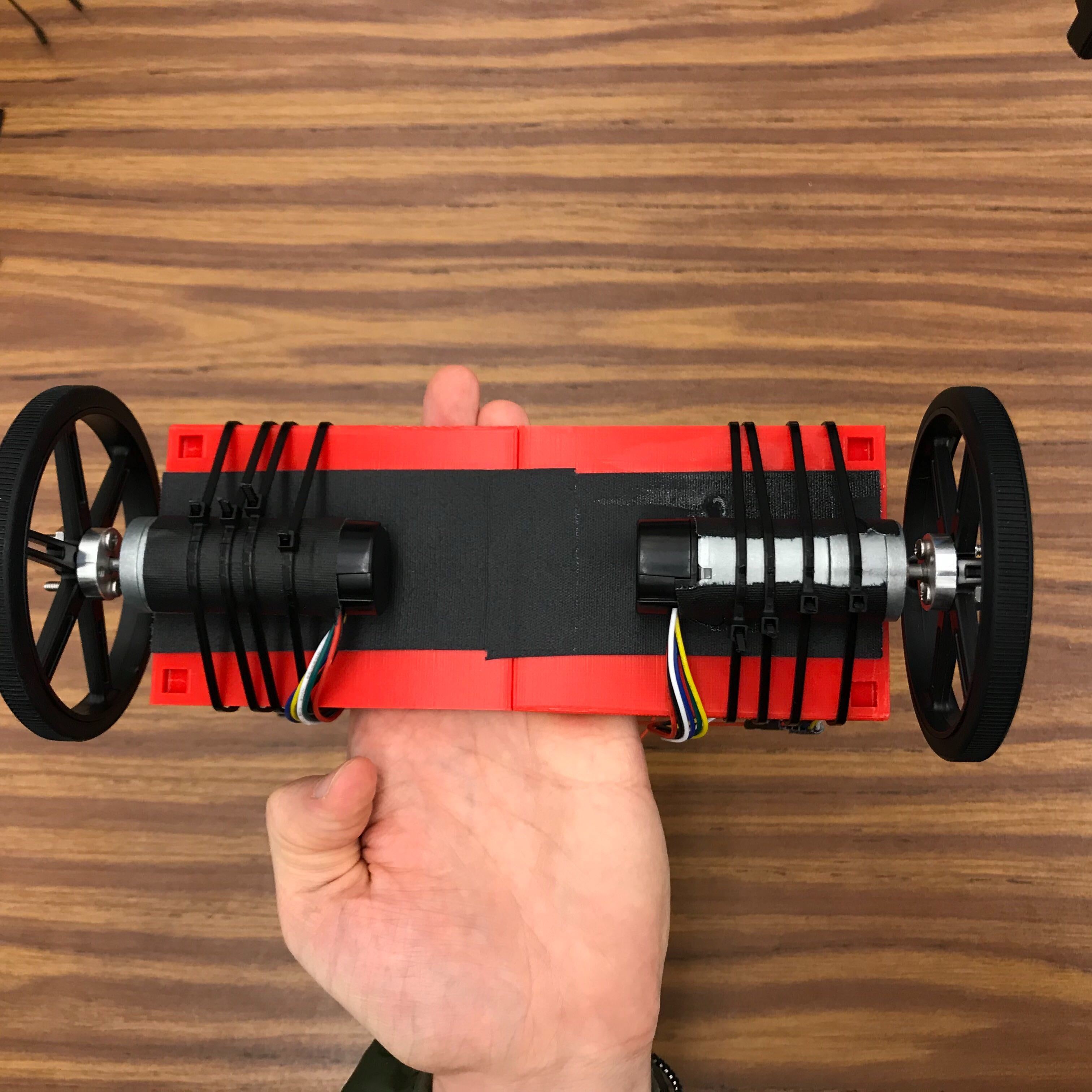
3. Assemble the Motors, Mounting Hubs and Wheels, which go underneath the base. We had to use super glue on the Hub-Motor connection to keep the wheels firmly in place, as well as super glue to adhere the motors underneath the base.
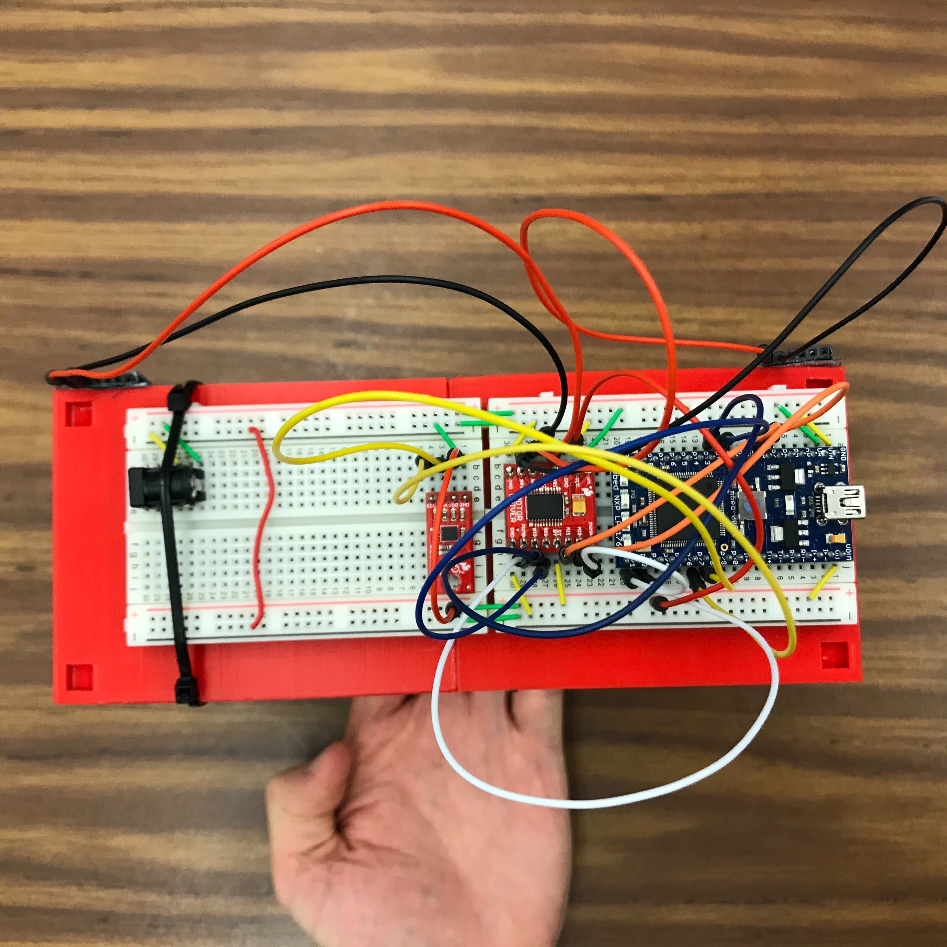
4. Connect the IMU, H Bridge, 5V power, and Mbed to the breadboards (the pinout tables are at the bottom of this document), and the breadboards to the top platform. Once everything is secure, connect the motors to the H Bridge.
Under the Bottom Platform
On top of the Top Platform
4. Compile and load the code onto the Mbed.
5. Connect power to the breadboard with the 5V power cord.
7. Run the Mbed and watch the 4180Balancer do its job!
Code
At the top, via import.
Hardware Setups
IMU
| Pin Label | |
|---|---|
| GND | GND |
| VDD | 3.3V |
| SDA | 28 |
| SCL | 27 |
H Bridge
| Pin Label | |
|---|---|
| VM | 5V |
| VCC | 3.3V |
| GND | GND |
| STBY | HIGH |
| AIN1 | 7 |
| AIN2 | 8 |
| BIN1 | 11 |
| BIN2 | 12 |
| PWMA | 21 |
| PWMB | 22 |
| A01 | Left Motor Red |
| B01 | Right Motor Black |
| A02 | Left Motor Black |
| B02 | Right Motor Red |
Mbed
| Pin Label | |
|---|---|
| GND | GND |
| Vin | 5V |
| 7 | AIN1 |
| 8 | AIN2 |
| 11 | BIN1 |
| 12 | BIN2 |
| 21 | PWMA |
| 22 | PWMB |
| 27 | SCL |
| 28 | SDA |
Left Motor
| Pin Label | |
|---|---|
| Red | A01 |
| Black | A02 |
Right Motor
| Pin Label | |
|---|---|
| Red | B02 |
| Black | B01 |
1 comment on 4180Balancer:
Please log in to post comments.
Really cool idea and program!