Live Etch-A-Sketch
Live Etch-A-Sketch - Created by Joshua Schrader and Brandon Yee
Introduction
The Live Etch-A-Sketch is a remotely controlled robot that replicates the drawing style of the original toy. The input controller wirelessly controls the DC motors of the Magician Robot. Rotation of the rotation sensor moves the robot horizontally and rotation of the right rotation sensor moves the robot vertically.
List of mbed components and peripherals used --
| 2x mbed LPC1768 | 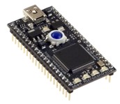 | Multi-turn Rotation Sensor | 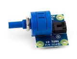 |
| Triple Axis Accelerometer Breakout - ADXL345 | 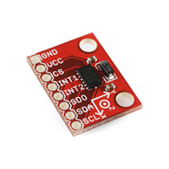 | IR LED Transmitter Module | 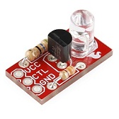 |
| Magician Chassis | 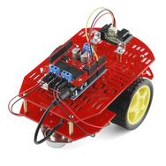 | 2x H-bridge driver breakouts 6V+ @1A or larger | 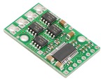 |
| Servo Motor and Controller |  | 8x AA Batteries |  |
| Wiring Kit |  | Small Breadboard |  |
How it works -

Input Controller
The input controller consists of two multi-turn rotation sensors, an accelerometer, an mbed, and the transmitter of the IR LED module. The mbed reads in data from the two rotation sensors and sends it serially to the transmitter. The IR transmitter then transmits the multi-turn rotation sensors’ outputs wirelessly to its receiver pair on the breadboard mounted on the Magician chassis. If the input controller is shaken, the accelerometer on the input board will tell the mbed to instead send an instruction to the IR transmitter to stop drawing and return to its starting position. In order for the stop instruction to not be sent at the slightest shake, the mbed will scan for a shake, wait for a set time, and scan for a shake again. If both shakes are confirmed, the mbed will then send the stop instruction.
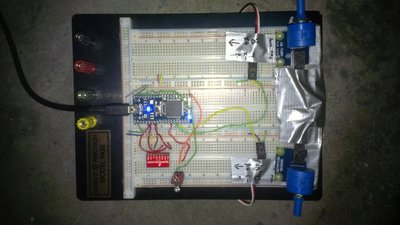
mbed's LEDs state
| LED1 | LED2 | LED3 | LED4 |
|---|---|---|---|
| Running | Shake Detected | +/-x | +/-y |
The source code used to program the mbed can be downloaded on the mbed site at http://mbed.org/users/theschrade54/code/EtchSketchController
Wiring between the mbed and the Right Rotation Sensor -
| mbed | Right Rotation Sensor |
|---|---|
| gnd | gnd |
| VU(5V) | Vcc |
| p15 | Ain |
Wiring between the mbed and the Left Rotation Sensor -
| mbed | Left Rotation Sensor |
|---|---|
| gnd | gnd |
| VU(5V) | Vcc |
| p16 | Ain |
The rotation sensors are typically used in Human Interface Applications and can measure 3600 degrees of rotation - 10 full turns.
Wiring between the mbed and the Accelerometer -
| ADXL345 Pin | mbed Pin |
|---|---|
| Vcc | Vout |
| SDA | p5 |
| SDO | p6 |
| SCL | p7 |
| CS | p8 |
Wiring between the mbed and the IR Transmitter -
| mbed | IR transmitter |
|---|---|
| gnd | |
| VU(3.3V) | Vcc |
| p13(TX) | gnd |
| p14(RX) | |
| p21 (PWM) | CTL |
Magician Robot Base Kit
The receiver of the IR LED module receives the instructions from its transmitter pair and transmits it serially to the mbed located next to it on the Magician chassis. The mbed interprets the inputs and translates it as vertical and horizontal movement. To do this, the robot will note its beginning position as facing at dy, dx = 0 and a modified Cartesian coordinate system is used such that 0 = +y, 90 = +x, 180 = -y, and 270 = -x. The mbed translates the input instructions and sends the new modified instructions to the H-bridge breakout to control the Magician chassis’ DC motors accordingly. If the instruction is to stop, the mbed will tell the servo to turn, lifting the pen off the floor, and return to the starting position.
mbed's LEDs states
| LED1 | LED2 | LED3 | LED4 |
|---|---|---|---|
| Drawing | Relocating | Left Wheel Moving | Right Wheel Moving |
The source code used to program the mbed can be downloaded on the mbed site at http://mbed.org/users/theschrade54/code/1EtchSketchDrawbot
Wiring between the mbed and the IR Receiver
| mbed | IR receiver |
|---|---|
| gnd | gnd |
| VU(3.3V) | Vcc |
| p13(TX) | |
| p14(RX) | DATA |
| p21 (PWM) |
Wiring between the Magician chassis' DC motors and the H-bridge breakout
| mbed | Dual H-bridge breakout | Robot DC motors | Battery |
|---|---|---|---|
| Vin | Vmot | + | |
| Gnd | Gnd | - | |
| Vout | Vcc | ||
| p21 | PWMB | ||
| p22 | BIN2 | ||
| p20 | BIN1 | ||
| p27 | AIN1 | ||
| p25 | AIN2 | ||
| p24 | PWMA | ||
| Vout | /STBY | ||
| A01 | left-red | ||
| A02 | left-blk | ||
| B02 | right-blk | ||
| B01 | right-red |
The 4 AA battery holder mounts on the lower deck next to the two geared DC drive motors. For standalone operation, the battery output is used to power mbed using the Vin pin and the battery gnd is connected to mbed gnd. The mbed's 5V supply cannot handle all of the motor current needed, so tie the motor driver's output stage directly to battery+.
Wiring between the mbed and the Servo
| mbed | Servo | Battery |
|---|---|---|
| gnd | - | |
| Vcc | + | |
| p23 | PWM |
Because the servo takes more power than the mbed can provide, the servo must be attached to a second 4 AA battery holder. You can place this one on the lower deck as well.
For more information on how to effectively interface with a motor, go to http://mbed.org/users/4180_1/notebook/sparkfun-magician-robot-base-kit/
Video Demo -
Problems Encountered and Future Steps
One of the main problems we faced was finding a way to wirelessly interface the input controller with the Magician Chassis. We first tried to use the Xbee wireless module but none of modules in lab worked. We tried debugging it but the best we could do was interface with the mbed and tell whether the mbeds were sending or receiving data respectively but not the Xbee transmitter/receiver themselves. Next we tried using an RF transmitter/receiver pair and we got it to work but it would output too much noise for us to use effectively. Below is a screenshot of the terminal displaying what the receiver mbed received from the RF receiver.
/media/uploads/Brandon/_scaled_rf_receiver_terminal.bmp
The last module we tried was the IR LED transmitter module and although it had some noise, it was much better than the RF’s. We decided to use this one for our project.
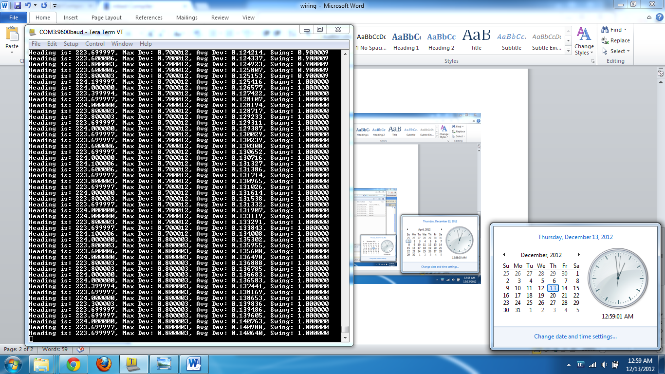
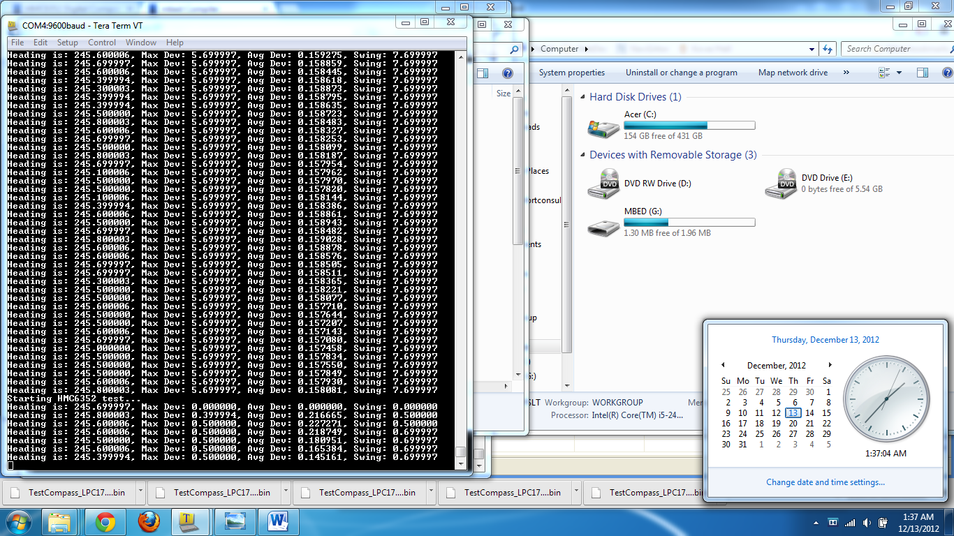
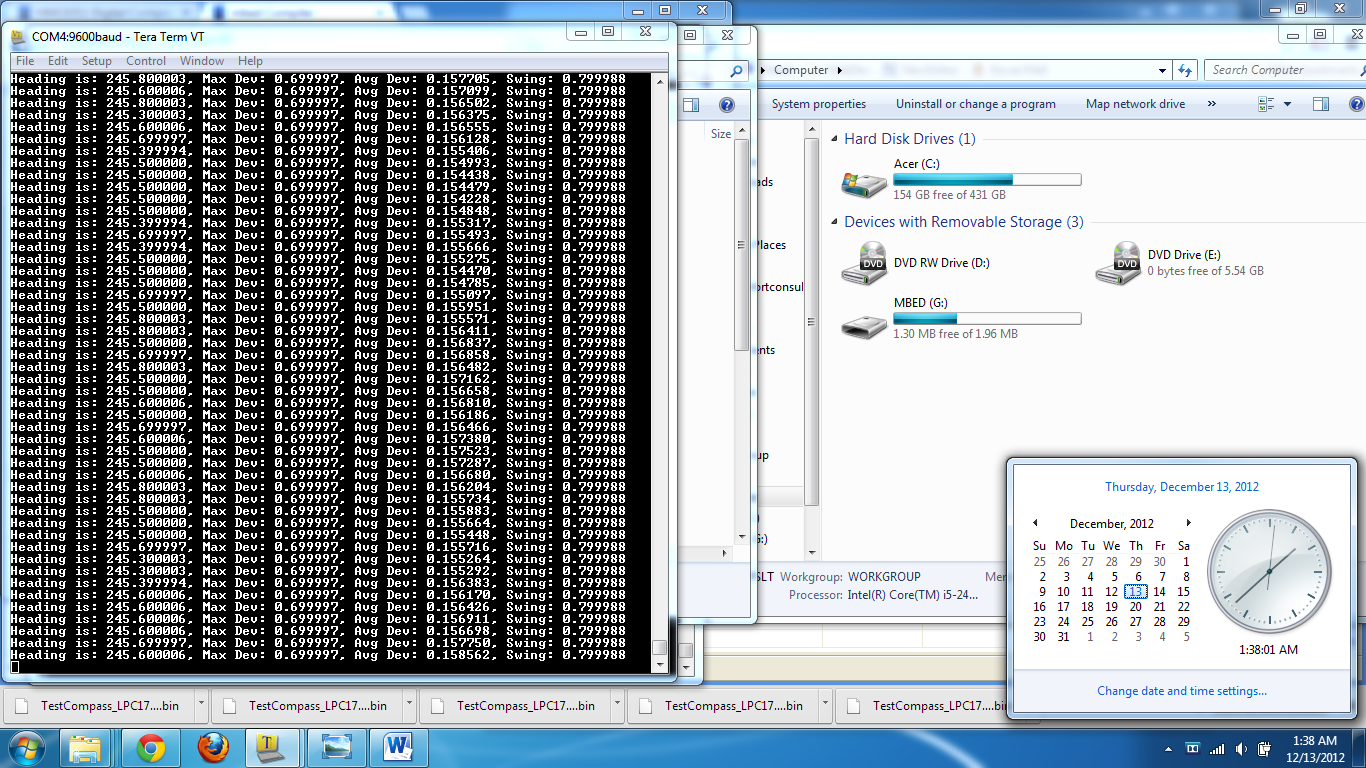
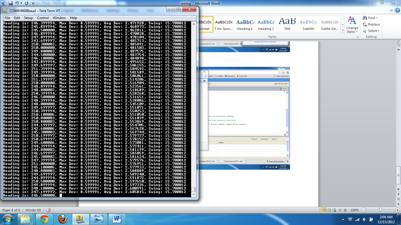
Another major problem we faced was using the HMC6352 Compass for the dead reckoning of our robot. The DC motors on the Magician chassis interfered with the compass’ readings and was unviable to use unless placed far away from the motors. Although we ended up rewriting our own personal code for detecting the location of our robot, the attempts with dead reckoning gave us a baseline for what to ignore for feedback.
No Motor
Motor present but off
Motor On
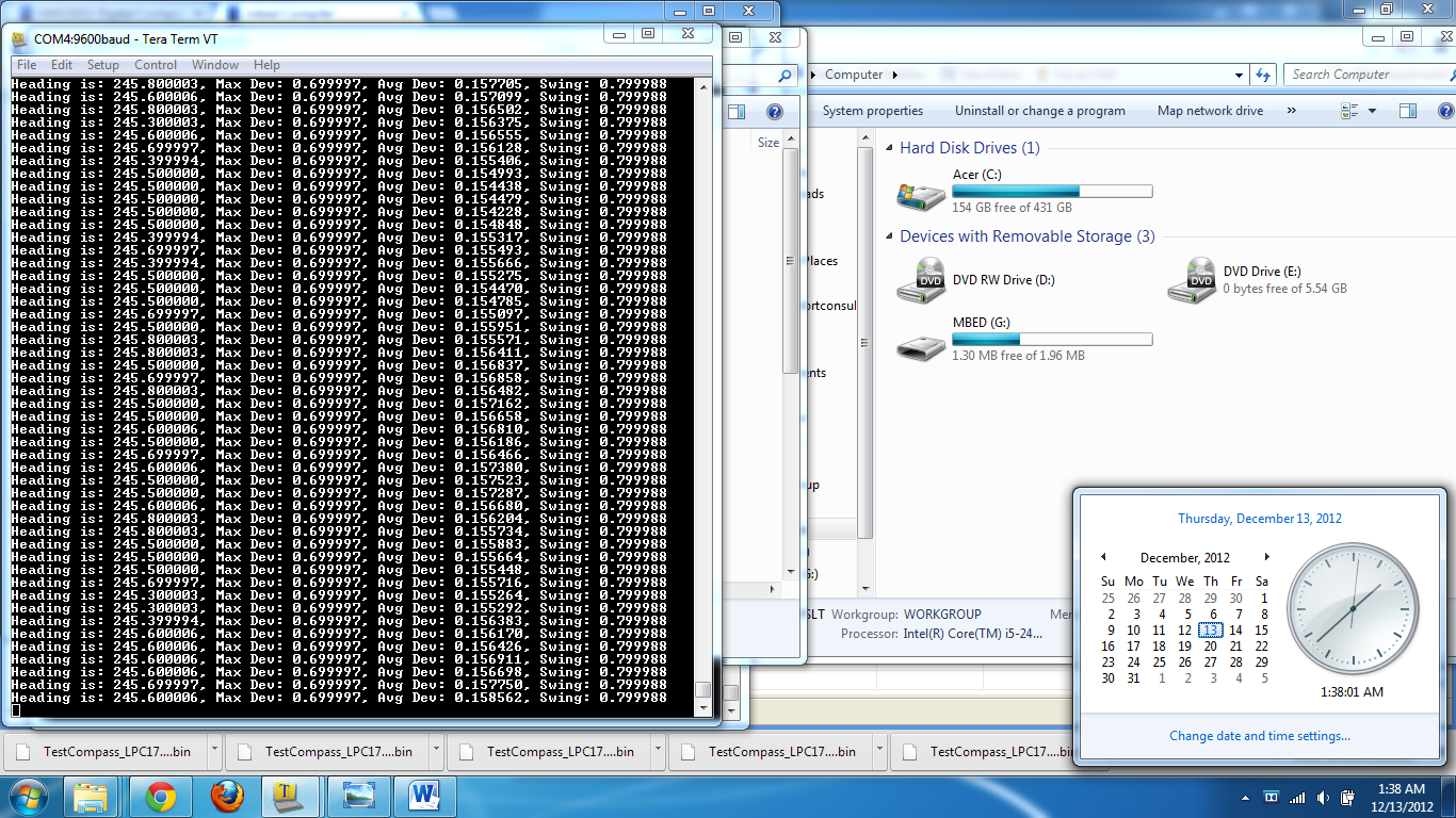
The code for dead reckoning can be found at http://mbed.org/users/theschrade54/code/TestCompass
For the future, we would like to implement full-scale dead reckoning to complete the automatic repositioning. Otherwise although we’ve spent many hours improving the accuracy and response time of the robot, more improvements would better the robot’s performance. Optionally, we could also have an LCD screen on the input controller that demonstrates how the robot should move so that the user can focus on the LCD screen for a top-down view rather than a potential side-view.
Thank you for reading!
Please log in to post comments.
