LED can be controlled by remote TCP client. This code was tested with WIZwiki-W7500 platform board.
Dependencies: WIZnetInterface mbed
Fork of TCP_LED_Control-WIZwiki-W7500 by
WIZwiki-W7500 TCP LED Control Example
Overview
The WIZwiki board series has an Ethernet interface with an RJ-45 connector, so you can quickly implement various network applications. This example controls the on-board LED by sending the specified command string to the board with Ethernet - TCP data.
Prerequisite
The following items are required to implement this example project.
- Mandatory
- WIZwiki-W7500 from WIZnet (Platform board with Ethernet I/F)
- USB cable
- LAN cable
- Optional
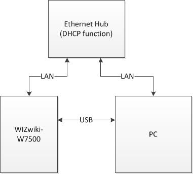
- Ethernet Hub or Router (supports DHCP IP allocation)
Information
If there is no Ethernet hub or router, you can connect PC and device directly with LAN cable.
Hardware Configuration
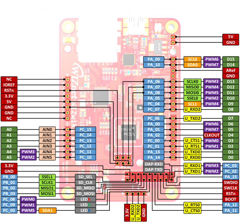
WIZwiki-W7500 Pinout

On-board LED
The on-board LED (red) used to verify the transmission of TCP data is connected to the PC_08 pin and is declared as LED1 in the mbed library.
Network Configuration

Firmware
Command String
The following three command strings are implemented in this example project.
- LED_ON
- LED_OFF
- LED_BLINK
- LED blinks every 200 milliseconds.
- Implemented using mbed Ticker APIs
Network Settings
MAC address
For Ethernet networking, each network device must have its own unique hardware address. that hardware address is called MAC address, and typically the MAC address is represented by six bytes hex separated by a colon. e.g., 00:08:DC:XX:XX:XX
The MAC address is defined in the code as follows.
main.cpp
#define MAC "\x00\x08\xDC\x55\x51\x52"
IP address allocation method
Use Static IP address
The 'Static IP address' setting is the default value, and the device is configured with the network information defined in the code. It can be used when connecting the device directly to the PC or through an Ethernet hub. The IP address of the PC should be set to the same ip address range as the device.
The network information is defined in the code as follows.
main.cpp
#define IP      "192.168.0.20"   // IP address
#define SUBNET  "255.255.255.0"  // Subnet Mask
#define GATEWAY "192.168.0.1"    // Gateway address
The following is an example of the PC's network settings that can connect with the device's settings.
| PC's network setting example | |
|---|---|
| IP address | 192.168.0.21 |
| Subnet Mask | 255.255.255.0 |
| Gateway address | 192.168.0.1 |
Use DHCP
Routers that support DHCP automatically assign a leased range of IP addresses to each connected devices. If your PC is connected to a router, uncomment the following define and the device will be automatically assigned network information.
main.cpp
#define USE_DHCP
The network information assigned by the router can be checked through the debug messages output to the serial terminal.
Building and Running an Example
Steps
1. Import this project into your mbed compiler.
2. View the default program source code and modify what you need.
- Network settings and so on.
3. Compile and Download the Program.
- To compile the program, click the Compile button in the toolbar. This will compile all the program source code files within the program folder to create a binary program.
- After a successful compile, you will get a "Success!" message in the compiler output and the download dialog will pop up. Save it to the location of the mbed Microcontroller drive, and then hit reset on the microcontroller to start it running!
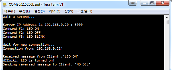
4. Run the serial terminal program and check the messages.

- Device's network settings and supported command strings.
- Default UART baudrate: 115200bps
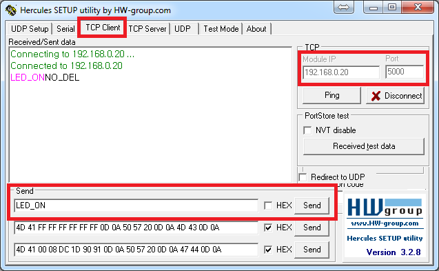
5. Run the TCP client terminal program and Connect to your device.

6. Send command to your device and check status of LED and serial messages


