You are viewing an older revision! See the latest version
Pulse Width Modulation
All exercises in this topic will be carried out using an mbed application board. mbed uses pins p21 to p26 for use with a PwmOut class. On mbed application board pins p21 and p22 are connected to a servo motor headers, pins p23, p24 and p25 are connected to a RGB LED, and p26 is connected to a speaker.
Exercise 1: Generating PWM signals
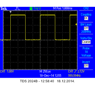
Create a PWM signal which can be seen on an oscilloscope. Set the frequency of the PWM signal to 1 kHz. Set the initial duty cycle to 50%.
A possible solution is given below.
Import programMAB_PWM_Oscilloscope_1
A simple 1 kHz PWM signal generator with 50% duty cycle.
An oscillogram is shown in the following figure:

Now modify the above program in a way that duty cycle changes with the setting of a potentiometer Pot1.
The solution is given below.
Import programMAB_PWM_Oscilloscope_2
A simple 1 kHz PWM signal generator with adjustable duty cycle over potentiometer.
Run the program and observe how the duty cycle changes with turning of Pot1.
Exercise 2: Controlling LED brightness with PWM
Create a program that controls a brightness of mbed onboard LED1 using PWM. The brightness must be set by using potentiometer Pot2.
The solution is given in the program below.
Import programMAB_PWM_LED1
A simple program that controls the LED1 brightness by using potentiometer.
