You are viewing an older revision! See the latest version
Digitalni izlazi i ulazi
mbed Hello World
Riješite sljedećih nekoliko zadataka s ciljem upoznavanja s mbed razvojnom platformom NXP LPC1768:
- Pročitajte uvodni dio o mbed LPC1768 mikroupravljaču. Provjerite da li je na vašem primjerku instaliran najnoviji firmware. Ako nije, instalirajte ga koristeći ove upute. Pokrenite Hello World program.
- Modificirajte program tako da blinkaju ostale 3 LED-ice.
- Modificirajte program tako da blinkaju 2 ili više LED-ica (gotovo) istovremeno.
- Modificirajte program tako da LED1 blinka 4 sekunde, nakon čega se LED1 isključuje, a počinje blinkati LED2 u trajanju od 4 sekunde. Zatim se isključuje LED2 i ciklus kreće ispočetka s LED1. Koristite
whileiforpetlje u ovom zadatku. - Pregledajte dokumentaciju klase
DigitalOut. Uključite ili isključite bilo koju LED-icu koristeći funkcijuwritekao pripadnicu klaseDigitalOut. Objasnite uloguoperator=u dokumentaciji klase.
U sljedeće dvije vježbe spojit ćete LED-ice na dva načina i usporedit ćete dva različita moda rada digitalnih izlaza.
Standardni digitalni izlazi s vanjskim LED-icama
Note
Za izvođenje sljedećih vježbi bit će vam potrebne dvije LED-ice, dva 220 ili 330 Ohmska otpornika, SPDT i SPST mehaničke sklopke (klizna sklopka i tipkalo), optički transmisivni i reflektivni senzori, žice, prototipna pločica (breadboard) i naravno mbed razvojna platforma.
Dobar tutorial o sklopkama (poles, throws, NO, NC, ...) možete pronaći ovdje i preporuča se da ga proučite.
Spojite komponente na prototipnu pločicu prema sljedećoj shemi spajanja:
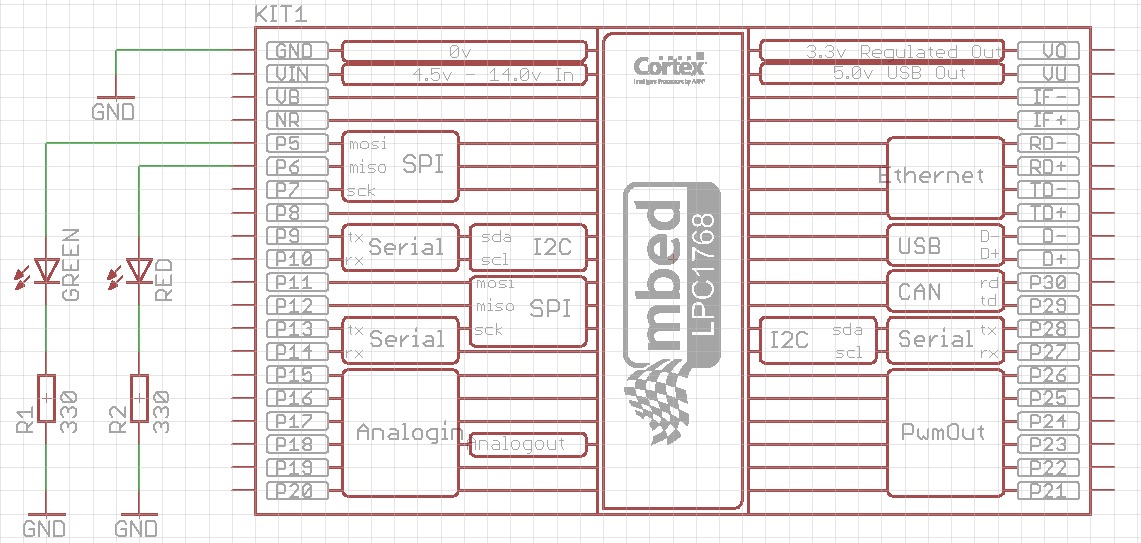
Proučite sljedeći programski kôd:
#include "mbed.h"

DigitalOut green(p5);
DigitalOut red(p6);

int main() {
    while(1) {
        green = 1;
        red = 0;
        wait(0.5);
        green = 0;
        red = 1;
        wait(0.5);
    }
}
Primijetite da su digitalni izlazi (p5 i p6) deklarirani pomoću klase DigitalOut, koja (još) nema podršku za postavljanje izlaznog moda. Pretpostavljeni (default) mod je standardni, u kojem je izlazni pin izvor (struja teče iz pina, odnosno unutarnjeg izvora, prema trošilu).
Pokrenite program. Trebali biste vidjeti naizmjenično blinkanje zelene i crvene LED-ice svakih pola sekunde.
Digitalni izlazi u modu otvorenog odvoda (open drain mode)
Spojite komponente na prototipnu pločicu prema sljedećoj shemi spajanja:
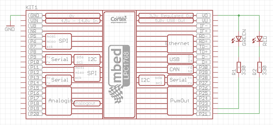
Proučite sljedeći programski kôd:
#include "mbed.h"

DigitalInOut green(p22, PIN_OUTPUT, OpenDrain, 1); // The first way of digital output configuration
DigitalInOut red(p21); // The second way of digital output configuration

int main() {
    red.output(); // Addition 1 for the second way of digital output configuration
    red.mode(OpenDrain);  // Addition 2 for the second way of digital output configuration
    red = 1; // Turn red LED off (inverse logic)
    while(1) {
        green = 1;
        red = 0;
        wait(0.5);
        green = 0;
        red = 1;
        wait(0.5);
    }
}
In this way the digital output pins are configured as open drain outputs. A class used for this purpose is DigitalInOut, since the standard class DigitalOut does not (yet) have the option for open drain mode. DigitalInOut class has two constructors, and both of them are used and commented in the example code above.
You may also notice the inverse logic of this configuration. When the output is set to logic 1 state, a potential of that pin is 3.3 V, so the potential difference (voltage) accros the LED and resistor is zero and LED is off. When the output is set to logic 0, the potential of that pin drops to 0 V, and voltage across the LED and resistor becomes 3.3 V and LED turns on.
Be careful!
If you connect the LEDs in the open drain mode (the second schematics) and you do not configure the outputs to be in the open drain mode, the LEDs will probably flash fine, but there is a high risk of damaging the mbed input circuitry! The open drain mode is sometimes the only way of driving your digital output (e.g. 7-segment display with common anode), so use it properly when necessary.
Digital input
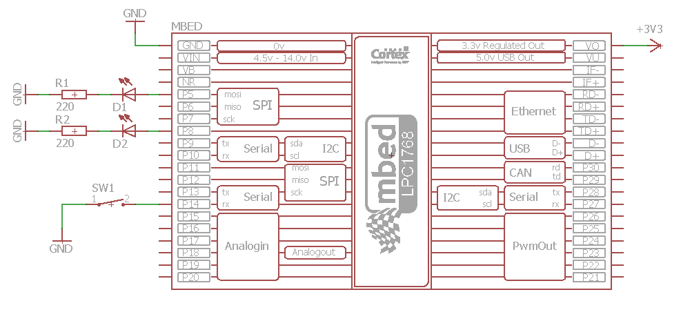
Add a single-pole double-throw switch to the first schematics with LEDs, as shown in the following figure:
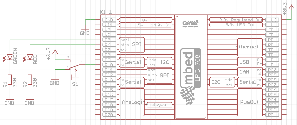
Examine the following code:
#include "mbed.h"

DigitalOut green(p5);
DigitalOut red(p6);
DigitalIn switchInput(p10);

int main() {
    int switchState;
    while(1) {
        switchState = switchInput; // read the input state only once in the while loop
        if(switchState == 0) {
            green = 0; // green LED off
            red = 1; // flash red LED
            wait(0.5);
            red = 0;
            wait(0.5);
        } else if (switchState == 1) {
            red = 0; // red LED off
            green = 1; // flash green LED
            wait(0.5);
            green = 0;
            wait(0.5);
        } else {
            // this case should not happen
            red = 1;
            green = 1;
        }
    }
}
Run the above program. You should see the red LED flashing when the switch S1 is in position #1, while the green LED is off, and vice versa when the switch is in position #3.
Now remove the wire that connects switch contact #1 with GND. Observe the behavior of the LEDs. You should see no difference comparing to the normal case. This means that the mbed input pin (p10) is connected to the GND internally, i.e. the pin is in the PullDown mode by default (we did not set the mode option at all).
Next, modify the program by setting the pin p10 into input mode PullUp. Immediately after the start of the main() function (line 8) add the following statement:
switchInput.mode(PullUp);
Run the modified program (leave the wire unconnected). You should now notice that the green LED flashes and the red LED is always off, regardless of the switch S1 state. The input pin p10 is internally pulled up when the switch S1 is in position #1.
Next, set the pin p10 into input mode PullNone (change the line 8 appropriately). Run the program and notice that the input pin p10 is now prone to external noise, static electricity or other electrical disturbances, when the switch S1 is in the position #1. The state of the LEDs are now unpredictable.
Finally, connect back the wire you removed and observe the behavior in all modes. The functionality of the program is now restored, regardless of the input mode set. To conclude this exercise, it is important to pull the input pin up or down (internally or externally) to have a reliable digital input state.
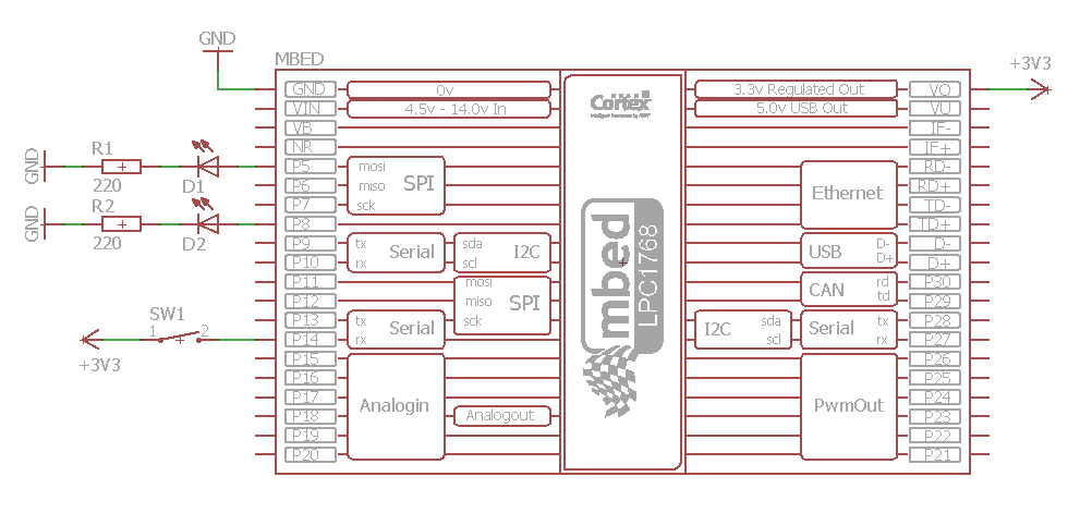
To conclude this exercise, replace the SPDT switch in the above schematics with SPST switch (push button), according to the following two schematics, and adjust the program accordingly to do the same tasks as above.
Counting events
In this exercise you will modify the above program to count the number of times the switch S1 has changed its state. If the count is less than 20, the green LED should be turned on and red off, and vice versa if the count is greater or equal to 20. Additionally, when the count reaches 20, wait 10 seconds after turning red LED on and reset the count to zero.
The code that solves this exercise is given below:
#include "mbed.h"

DigitalOut green(p5);
DigitalOut red(p6);
DigitalIn switchInput(p10);

int main() {
    int switchState, previousSwitchState = -1, x = 0;
    while(1) {
        switchState = switchInput; // read the input state only once in the while loop
        if (previousSwitchState == -1)  // first loop run
            previousSwitchState = switchState; // no changed state in the first loop run
        if (previousSwitchState != switchState)
            x++; // increase the count because the switch state is changed
        if(x < 20) {
            green = 1; // green LED on
            red = 0; //  red LED off
        } else {
            green = 0; // green LED off
            red = 1; //  red LED on
            wait(10);
            x = 0;
        }
        previousSwitchState = switchState; // refresh the previousSwitchState
    }
}
Analyze the code, run the program, and count how many times you need to change the switch S1 state for the red LED to turn on. You should expect this count to be 20, but in practice it will be much lower. The reason is a so called bouncing effect, which will be discussed later in the following exercises.
Optical sensors
Connect the components on the breadboard according to the following schematics:
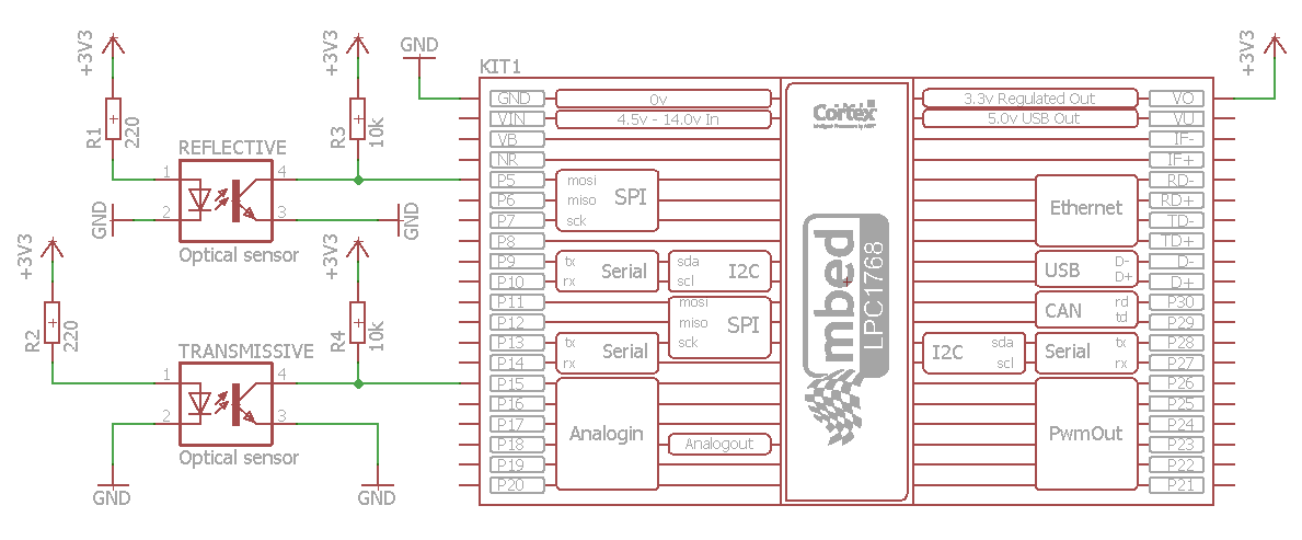
Write the program that will turn mbed's LEDs (LED1 and LED2) on/off based on the states of transmissive and reflective optical sensors.
Congratulations!
You have completed all the exercises in the Digital inputs and outputs topic.
Return to TVZ Mechatronics Team Homepage.
