Puppet Master System
Team Members
- Blake Strickland
- Eric Estevez
- Faraz Yousuf
Introduction
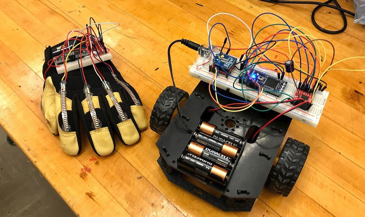
The Puppet Master System provides users with the capability of controlling a robot by having a glove that is equipped with flex sensors that send data to the robot based on what fingers are flexed.

Parts List
- 2 x XBee S2 Chips
- 2x XBee Explorers
- 5 x Flex Sensors
- 5 x 100 K Resistors
- Shadow Bot Kit
- H-Bridge
- 2 x mBed
- Glove
Connections
Glove
The glove is comprised of a mBed, 5 x Flex Sensors, 5x 100k resistors, and an XBee. Continue reading for further details.
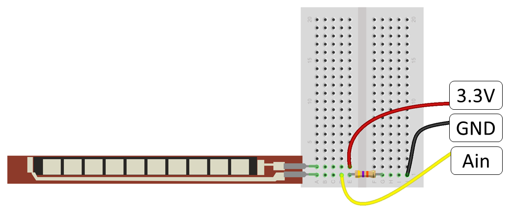
Simple Example of Flex Sensor Circuit:

Now that you understand the simple example above, let's discuss the circuit used in this project. Below, flex sensors are shown as variable resistors (aka. two terminal potentiometers). The flex sensor resistor value range depends on the sensor. Our flex sensor values were approximately 100k ohms (ignore typo on diagram). It is best practice to pair the flex sensor with a resistor of the same value. We tried multiple pairings until we got the widest range between open and closed hand. Keep in mind the code includes some constant variables used to calibrate the open and closed hand. After calibration, the processed glove inputs become float values scaled and constrained between 0 (closed hand) and 1 (open hand).
Flex Sensor Wiring Diagram with Pinout:

mbed-XBee Serial Connection:
| mbed | XBEE |
|---|---|
| VOut (3.3V) | VCC |
| Gnd | Gnd |
| TX=P9 | DOut |
| RX=P10 | DIn |
| P11 | RST |
Robot
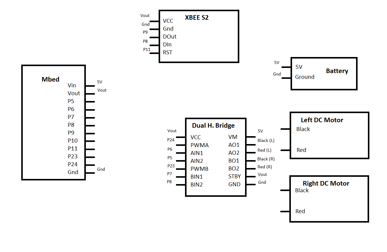
The robot is comprised of a mBed, an H-Bridge, 2x DC Motors, and a XBee.
| mbed | XBEE |
|---|---|
| VOut (3.3V) | VCC |
| Gnd | Gnd |
| TX=P9 | DOut |
| RX=P10 | DIn |
| P11 | RST |
Robot wiring diagram:

XBee Setup
To ensure fast connections between the two XBee you will need to set up a network between the two chips using the XCTU software. Download the XCTU software that will help with the setup. Using this software you will be able to setup one XBee as the Coordinator that will relay information and set up the network, and an End Device that can receive commands from the Coordinator.
To begin, connect the XBees to your computer using the XBee explorers. Open XCTU and add the devices via their COM ports. Once you have selected the two devices, not their MAC addresses which are also available at the bottom stickers of the XBee.
Select one of the XBee chips on the left, and then on the top select the "Update" button. Select the Coordinator AT and then write to the chip by clicking the pencil icon on top. You will have to hit the reset button on the appropriate chip. Select the other XBee chip but this time update it with the End Device AT firmware.
Return to the Coordinator XBee and type in a PAN ID. The ID number can be anything within the prompts specified range, but both chips need to have the same PAN ID. Scroll down to the networking section and note where it says SL and SH (Serial High and Low). Not these values.
Select the End Device XBee and type in the PAN ID you selected from the Coordinator. Scroll down to the networking area and note the SL and SH numbers. Then scroll down to DL and DH. In DL area enter the SL value of the Coordinator. In the DH area, enter the SH value of the Coordinator. Write to the XBee and then return to the Coordinator and repeat this step by inserting the SL and SH of the End Device into the DL and DH values into the Coordinator.

You can also name the XBee by scrolling to where it says Node Identifier. Also, make sure that both chips have the same baud and sampling rates. You can test communications between the two XBees by selecting the Console icon in the upper right-hand corner. Once you connect the two XBee in the console, by selecting the icon with an outlet on it, you can type in ASCII characters that should show up on the other XBee.
Control Scheme
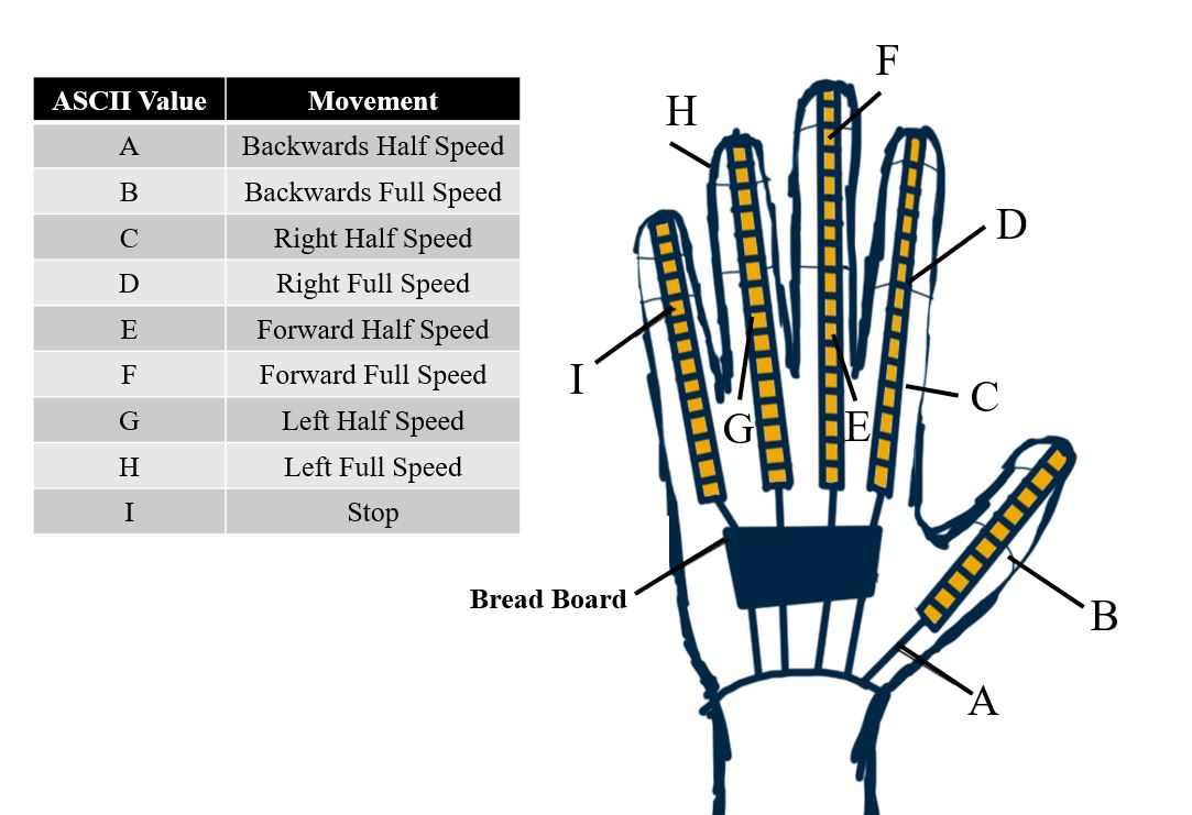
It is possible to setup the XBee pins as Analog or Digital I/O pins using the XCTU software. However, if you wish to refer to those specified pins, you have to identify the pin each time you write to it using the serial commands rather than only have to identify the pin once. Because of this, we decided to send ASCII characters between the XBee that will control the robot. Each finger has two ASCII characters assigned, which correlate to different speeds. Different flex levels output different ASCII characters. In addition, LED outputs are provided to indicate which direction the robot is moving and whether or not the network between the two XBee chips has been established. When all LEDs on the robot are active, the network has been established and is in the "I" stop state.

Source Code
The project uses two mbeds; one on the glove and one on the robot. Please see the following two sections for more detail on each.
Glove Code (Coordinator)
The glove is equipped with five flex sensors and the XBee that is setup as the Coordinator.
Import programGlove_transmit_Coordinator_Final
Final Version
Robot Code (End Device)
The glove is equipped with two motors and the XBee that is setup as the End Device.
Import programRobot_Puppet_EndDevice_Final
Final Version
