battery
Battery
Overview

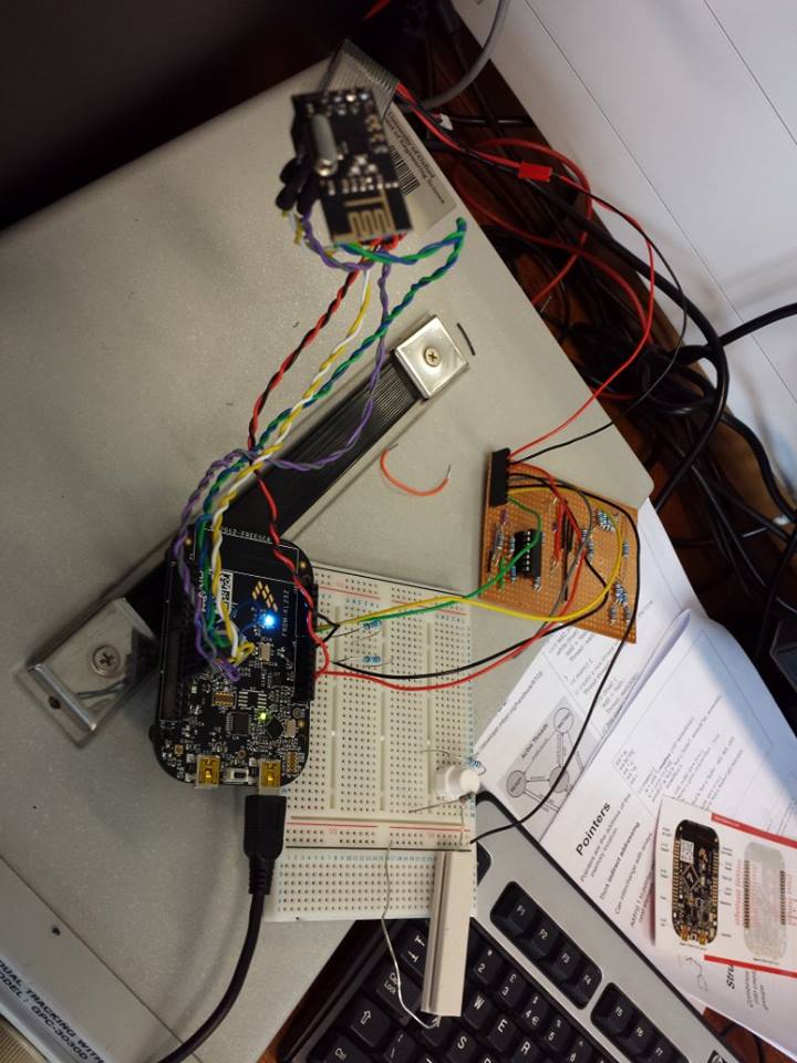
The Battery will be of large capacity to provide power for up to three light bulbs, potentially for several days. For the prototype, it is simulated by a small lithium-ion battery. The pack will have to be smart so an mbed microcontroller is included to measure and report usage. There are three modes:
1. Charging in the locker at the base station
2. Powering appliances
3. Idling
Functions
Charging
1) Power & Energy
a) The current level of charge
b) How much power has gone into the battery in this cycle
c) The current power going in
d) Estimated time left until fully charged 2) Transfer usage data to base station
Powering
1) Power & Energy
a) The current level of charge
b) How much power has been supplied
c) The current power / voltage / current out
d) Estimated time left until empty at current rate of consumption
2) Data Logging
a) Rolling averages of power out & voltage
b) Total time in use
c) Total time idling
3) Interface
a) Display the current level of charge as colour on the led.
4) Data saving
a) Force the battery into idling mode when it is nearly empty.
Idling
1) Display current level of charge on demand, e.g.: button press.
Technical implementation
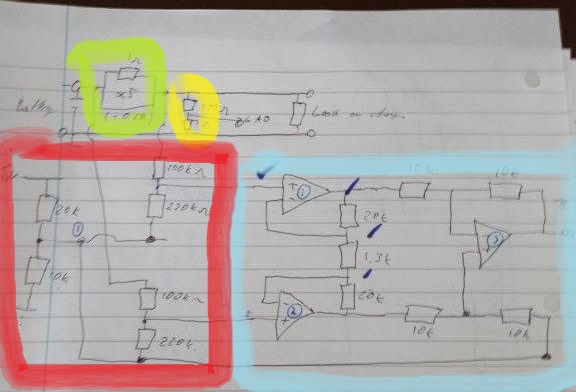
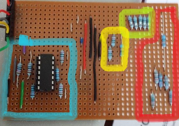
green-current resistor
red-potential divider for amp inputs
cyan-instrumentation amp
yellow-voltage sensor
Circuit Diagram

Board Layout

Voltage
Used a potential divider to bring voltages within range of ADC. From 5v max to 2.5v max.
Current
Used a bank of five 1 ohm resistors to create a small potential difference over which we could amplify using an instrumentation amplifier. This gives us a voltage that would be accurate enough under our ADC. This measurement is used with our Voltage to calculate the level of charge and power.
Our instrumentation amplifier required two potential dividers on the inputs in order the bring the measurement voltages away from the rail voltages of 5v and 0v. We calculated a required gain of 15.5 in order the bring the voltage within range of the ADC (from 8.5mV).