Important changes to forums and questions
All forums and questions are now archived. To start a new conversation or read the latest updates go to forums.mbed.com.
5 years, 1 month ago.
Is LPM013M126A worked by python in raspberry pi?
Dear JDI Support,
I would like to ask you about your LPM013M126A .
Is LPM013M126A worked by python in Raspberry Pi?
I am trying to use your LPM013M126A and a conversion board set released by Switch-Science with my Raspberry Pi zero W.
https://www.switch-science.com/catalog/2874/
Raspbian verion is:
| No LSB modules are available. | |
| Distributor ID: | Raspbian |
| Description: | Raspbian GNU/Linux 9.1 (stretch) |
| Release: | 9.1 |
| Codename: | stretch |
Wiring and codes were based on the website at:
https://qiita.com/inachi/items/79d14ef0bc5b044d5dd4
and showed below at table1 and code 1, respectively.
When I run code 1, segmentation fault occurs at line 25.
Would you show me where is wrong?
I want to display a bitmap image on the LPM013M126A in the end.
Thank you for your help.
Sincerely,
Toshihiko Takeshima
table 1
| Raspberry Pi | Display | ||
|---|---|---|---|
| GND | GND | ||
| IO 26 | IO 0 | DISP | |
| IO 11 | SPI0_SCLK | IO 14 | SCLK |
| IO 9 | SPI0_MISO | IO 12 | |
| IO 10 | SPI0_MOSI | IO 13 | SI |
| IO 8 | SPI0_CE0 | IO 15 | SCS |
code1.py
import spidev
import time
import RPi.GPIO as GPIO

channel = 0
disp = 26

GPIO.setmode(GPIO.BCM)
GPIO.setup(disp, GPIO.OUT)

GPIO.output(disp, True)
time.sleep(1)
GPIO.output(disp, False)
time.sleep(0.1)

cmd_buff = bytearray(92)
cmd_buff[0] = 0x88
cmd_buff[1] = 1
for i in range(88):
	cmd_buff[i+2] = 0x11

spi = spidev.SpiDev()
spi.open(0, 0)
time.sleep(0.1)
resp = spi.xfer2(cmd_buff)
time.sleep(0.1)
spi.close()
time.sleep(0.1)

GPIO.output(disp, True)
time.sleep(1)
GPIO.output(disp, False)
time.sleep(0.1)

GPIO.cleanup()
Question relating to:
1 Answer
4 years, 11 months ago.
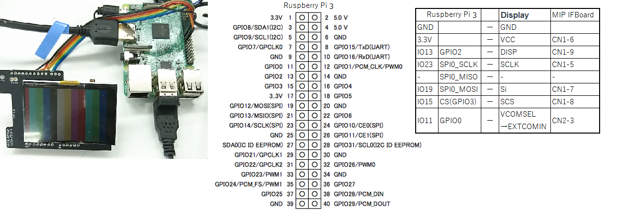
We confirmed the MIP connection with the Python sample program that displays the color bar on the MIP(LPM027M128C) that works with Ruspberry-Pi 3.
In the case of the LPM013M126A, please change the number of pixels and the number of lines. (400x240 -> 176x176).
For the process of converting BMP files to MIP format, please refer to the MBED MIP-Library sample code .
Thanks.

Backlight control added (May 30, 2019)
 refer to https://os.mbed.com/media/uploads/STakayama/jdi_mip8_lcd_last.pdf
Thanks.
- Raspberry pi3 model b+
- MIP Interface Board : https://www.switch-science.com/catalog/5393/
- LPM027M128C with BackLight : https://www.j-display.com/product/reflective.html
MIP_ColorBar.py
import spidev
import time
import RPi.GPIO as GPIO

channel = 0
disp = 13
scs = 15
VcomSel = 11

spi = spidev.SpiDev()
spi.open(0, 0)
spi.mode = 0b00     #SPI MODE0
spi.max_speed_hz=2000000   #MAX 2MHz
spi.no_cs
time.sleep(0.1)     #Wait

GPIO.setmode(GPIO.BOARD)
GPIO.setup(disp   , GPIO.OUT)
GPIO.setup(scs    , GPIO.OUT)
GPIO.setup(VcomSel, GPIO.OUT)

GPIO.output(scs, 0)     #1st=L
GPIO.output(disp, 1)    #1st=Display On
#GPIO.output(disp, 0)   #1st=No Display
GPIO.output(VcomSel, 0) #L=VCOM(1Hz)
time.sleep(0.1)

GPIO.output(scs, 1)
time.sleep(0.000006)
spi.xfer2([0x20,0]) # ALL CLEAR MODE
GPIO.output(scs, 0)
time.sleep(0.000006)

#Color Bar
cmd_buff = bytearray(202)
cmd_buff[0] = 0x90  #'1x01xxyy=4bit mode,
cmd_buff[1] = 0x00  #Line
for i in range(200):
    k=i>>4
    cmd_buff[i+2] = (k<<5)&0xe0 | (k<<1)&0xe #R0,G0,B0,D0,R1,G1,B1,D1

#Buffer->MIP
GPIO.output(scs, 1)
time.sleep(0.000006)
for j in range(240):
    cmd_buff[1] = j  #line(M128A=240lines)
    resp = spi.xfer2(cmd_buff)
time.sleep(0.000006)
GPIO.output(scs, 0)
time.sleep(0.1)

#BackLight ---------------------------------------- May 30, 2019
GPIO.setup(7,GPIO.OUT)      #Pin7 = GPIO4
p7=GPIO.PWM(7,60)
p7.start(0)
for x in range(100):
    for pw in range(0,100,1):
        p7.ChangeDutyCycle(pw)
        time.sleep(0.05)
    for pw in range(100,0,-1):
        p7.ChangeDutyCycle(pw)
        time.sleep(0.05)

p7.stop()
#-----------------------------------------------------

spi.close()

GPIO.output(disp, 1)
time.sleep(0.1)

#GPIO.cleanup()
Thank you for reply and sorry for late reply to your confirmation. I will check in my system according to your answer.
Again thank you very much for your time and kindness.
Toshihiko Takeshima
posted by 17 May 2019Thank you for your code and connection very much. I confirmed with LPM027M128C and Raspberry Pi Zero.
I want to use the backlight function. Would you like to show the connection and python code? (python version of ifswPWM in MIP8f_FRDM_sample/main.cpp)
(In Japanese) コードと接続情報、ありがとうございます。 当方、Raspberry Pi Zeroで動作確認が出来ました。 感謝しきりです。
もしよろしければ、バックライトの接続およびpythonコードをご教示いただけますでしょうか。 (MIP8f_FRDM_sample/main.cppのifswPWMあたりを想定しています)
posted by 20 May 2019
I will check your program. Let me confirm a question. We would like to confirm VCC3.3V to the LCD and VBUS-5V to the BackLight circuit, and VCOM for LCD. Thanks.
posted by Shinichi Takayama 15 May 2019