Important changes to forums and questions
All forums and questions are now archived. To start a new conversation or read the latest updates go to forums.mbed.com.
7 years, 6 months ago.
ADC configuration problem on LPCXpresso54114
Hello, guys.
I am working on a project on LPCXpresso54114 board with mbed library.
When I want to use functions related to ADC for reading analog input. I find there is a problem on it by which I cannot read the correct value of analog input.
Here is my code. It is very simple, just construct a instance of AnalogIn class and use that instance to read analog input.
problem code
#include "mbed.h"

AnalogIn ain(A0);

int main(){
    uint16_t captured_value = 0;
    while (true){
        captured_value = ain.read_u16();

        printf("Captured value: %u. \r\n", captured_value);
        printf("Captured voltage: %3.2fV. \r\n", (float)captured_value * (3.3f / (float)0xFFF));
        printf("-----------------------------------------------\r\n");

        wait(0.5);
    }
}
A rotary potentiometer is used to change the value of analog input. And in the same time I use a Arduino UNO as a comparison to check if the captured voltage is correct.
Here is the captured values of LPCXpresso54114. Since there is a 12-bit ADC on LPCXpresso54114, the captured values should be in range from 0 to 4095.
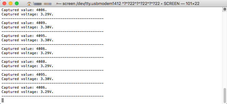
Here is the captured values of Arduino UNO in the same time as the previous figure. Depending on the behavior of Arduino, for the voltage ranged from 0 to 3.3V, the captured values should be in the range from 0 to 675.
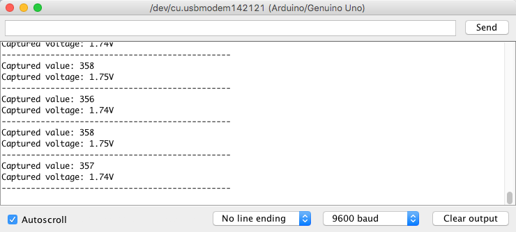
We can see there are differences between the captured values by two devices. After changing the value of potentiometer, I find that no matter how much I change the potentiometer, the captured value of LPCXpresso54114 is always a constant value. The captured values by Arduino UNO are compliant with the changing behavior of the potentiometer. This means there should be some problem during data capture in LPCXpresso54114.
When the captured value of a GPIO is incorrect, the first idea comes to my mind for locating the problem is checking the content in the IOCON register of that specific pin. To check if the IOCON register of PIN A0 is configured correctly, I add following lines in my code:
check IOCON
    PinName pin = A0;

    uint32_t pin_number = pin & 0x1F;
    uint8_t port_number = pin / 32;

    printf("IOCON of Pin [%d][%lu]: 0x%04lx. \r\n", port_number, pin_number, IOCON->PIO[port_number][pin_number]);
The value of IOCON register read from the code above is 0x01a0 as shown in following figure:
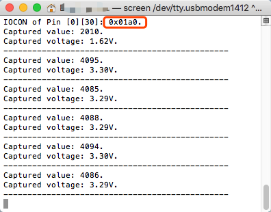
In data sheet, it reads: to enable analog function of P0_30(A0), the 7th bit which is DIGIMODE bit of the IOCON register should be set to 0. That means if the IOCON register is configured correctly, the value should be 0x0120. But now it is 0x01a0. It seems that it fails to configure the IOCON register.
Then I clear the DIGIMODE bit manually in my code with following lines:
manually change DIGIMODE
    PinName pin = A0;

    uint32_t pin_number = pin & 0x1F;
    uint8_t port_number = pin / 32;
    // clear DIGIMODE bit in IOCON register
    uint32_t reg = IOCON->PIO[port_number][pin_number] & ~IOCON_PIO_DIGIMODE_MASK;
    IOCON->PIO[port_number][pin_number] = reg;

    printf("IOCON of Pin [%d][%lu]: 0x%04lx. \r\n", port_number, pin_number, IOCON->PIO[port_number][pin_number]);
After recompile and upload my code, the captured values of both devices are more or less the same. Captured values of LPCXpresso54114:
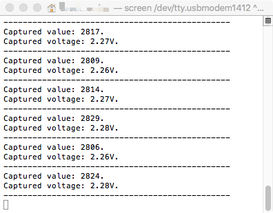
Captured values of Arduino UNO:
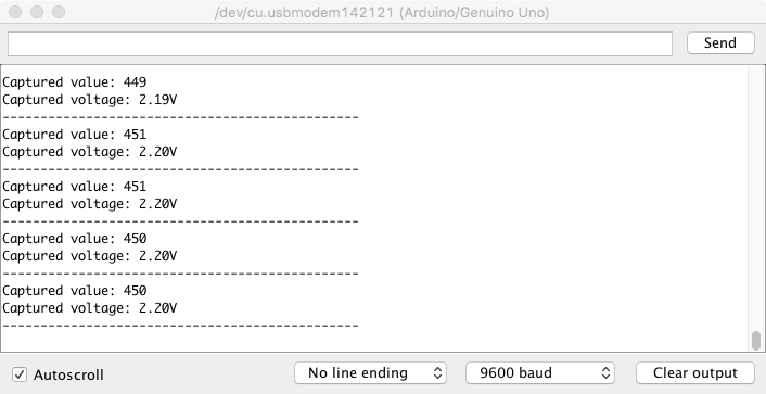
It ensures my assumption that the problem is "fail to clear DIGIMODE bit of the IOCON register". Then I want check when the problem occurs. After some experiments, I find there problem occurs during initialization of the analog pin. It seems that the initialization time of analog pin is not sufficient. By this reason the configuration of DIGIMODE bit of the IOCON register fails.
In following part, there is the construction function of AnalogIn class:
code of AnalogIn class
    AnalogIn(PinName pin) {
        lock();
        analogin_init(&_adc, pin);
        unlock();
    }
If I put a printf() into this function before analogin_init(&_adc, pin), the ADC works even I don't configure IOCON register manually:
printf() in AnalogIn class
    AnalogIn(PinName pin) {
        printf("hello world\r\n");
        lock();
        analogin_init(&_adc, pin);
        unlock();
    }
However, if I put there a wait() function or a loop instead of a printf(), the ADC doesn't work even in the case that wait() function works and the loop iterates enough times.
The code by which ADC doesn't work 1:
wait() in AnalogIn class
    AnalogIn(PinName pin) {
        wait(1);
        lock();
        analogin_init(&_adc, pin);
        unlock();
    }
The code by which ADC doesn't work 2:
a loop in AnalogIn class
    AnalogIn(PinName pin) {
        for(volatile int i=0; i<10000000; i++);
        lock();
        analogin_init(&_adc, pin);
        unlock();
    }
If the problem is related to time issues, It is very strange that only printf() works, but wait() and loop doesn't work.
More than this, I find another solution for the problem which ADC doesn't work. That solution is even more weird that if I use a DigitalOut in my code together with AnalogIn and I write the code in sequence:
second solution
    DigitalOut dout(LED1);
    AnalogIn ain(A0);
LPCXpresso54114 could read correct analog input. But if I reverse them like:
second solution incorrect
    AnalogIn ain(A0);
    DigitalOut dout(LED1);
The ADC doesn't work again. Does it mean during DigitalOut configuration, some other configuration related to AnalogIn is done in the same time? Or DigitalOut configuration just give MCU enough time to prepare AnalogIn configuration?
Is there anyone know why the mbed ADC driver works so weird for LPCXpresso54114?
Thank you for your help.
Regards,
Wenlong