Important changes to forums and questions
All forums and questions are now archived. To start a new conversation or read the latest updates go to forums.mbed.com.
8 years, 8 months ago.
mbed time delay interfacing with LabView (code and GUI below)
Hello,
I have been working on a small personal Labview/mbed project which is currently capable of functioning the brightness of the 4 LED's and read the two potentiometers.
Unfortunately there seems to be some lag on the mbed which seems to be overloaded by the data passing in and out through the usb port. I have seen some other posts which discuss reducing the baud rate. I suppose the main aspect to consider is the actual bandwidth on the USB cable which I believe has a maximum bandwidth 60MB/s.
Not sure whether LabView can show how many bytes of data are passing through the USB port during the run of the simulation?
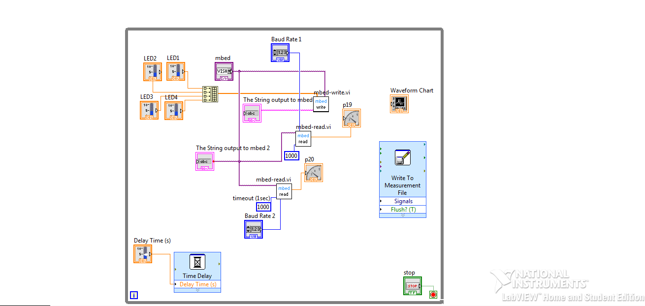
Here is the Block Diagram

I did try to build an array block for the mbed application board pots using the mbed read block similar to that created for the LED's however that didn't seem to work for outputs. Please feel free to provide any alternatives upon how to build something similar to an array block where by more outputs can be connected to one mbed read block. I did try connecting p19 and p20 to one read block however the issue was that when one of either pots were moved on the mbed application board both Gauges were caused to move, therefore an undesired outcome.
Feel free to have a go and if you manage to find a way to improve response time, then you are more than welcome to post it.
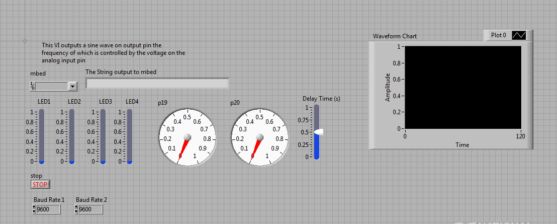
Here is the Front Panel

Here is the code compiled for the mbed
//libraries included
#include "mbed.h"
#include "mbed.h"
#include "C12832.h"
#include "LM75B.h"

Serial pc(USBTX, USBRX); //create the interface on the USB Serial Port
C12832 lcd(p5, p7, p6, p8, p11); //pins for LCD screen
PwmOut myled(LED1), myled2(LED2), myled3(LED3), myled4(LED4); //LED's on C12832 from library
AnalogIn pot(p19), pot2(p20); // potentiometers on C12832
AnalogIn anain(p15), anain2(p16), anain3(p17), anain4(p18); //analogue input using ANALOG IN ports
PwmOut pwmo(p21), pwmo2(p22), pwmo3(p23), pwmo4(p23), pwmo5(p24); // output PWM
DigitalOut digo(p25), digo2(p26); // output digital using PWMOUT ports
LM75B sensor(p27,p28);

int main()
{
    while(1)
    {
        lcd.cls();
        lcd.locate(0,0); //clears LCD
        // declare floats for labview LED parameters
        float brightness, brightness2, brightness3, brightness4;
        // mbed scans values from labview interface
        scanf("%f,%f,%f,%f", &brightness, &brightness2, &brightness3, &brightness4);
        // make LED's equal to labview values
        myled = brightness, myled2 = brightness2, myled3 = brightness3, myled4 = brightness4;
        // makes labview interface acquire pot
        printf("%.1f,\n", pot.read());
        printf("%.1f,\n", pot2.read());
        lcd.locate(0,3); //column 0, row 3
        lcd.printf("Pot 1 = %.1f\n", pot.read()); //print to LCD screen
        lcd.printf("Pot 2 = %.1f\n", pot2.read()); //print to LCD screen
        //wait(0.25);
    }
}
Will let you know if I get any further ahead in due course. Otherwise drop a line with any ideas!
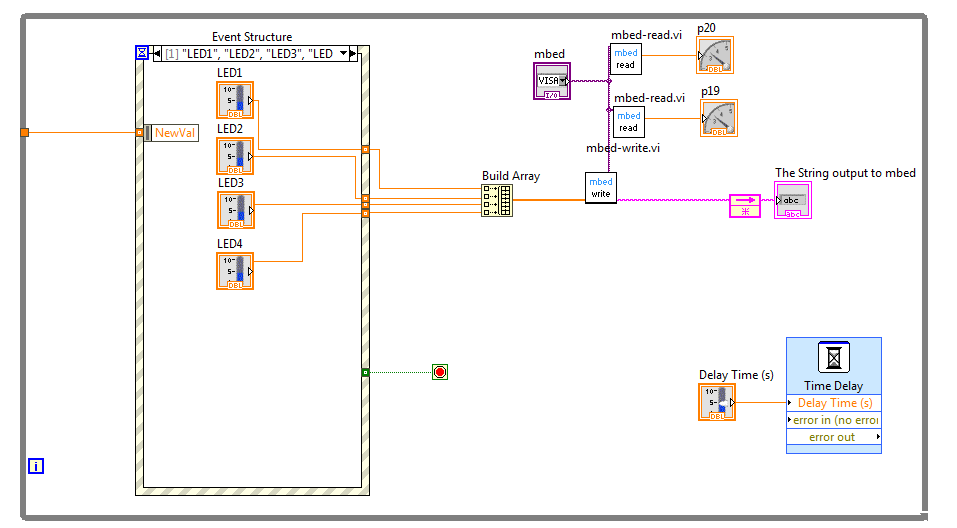
After some time I managed to use the event structure that managed to get all the LED's turned off upon using the STOP button.

The only issue I seem to have now is the fact that the while loop waits for the event structure before updating the controls on the front panel. Does anyone have any ideas how to place a condition for the while loop to continue reading and writing using the event structure.
Cheers!
1 Answer
Assigned to 8 years, 7 months ago.
This means that the question has been accepted and is being worked on.