Important changes to forums and questions
All forums and questions are now archived. To start a new conversation or read the latest updates go to forums.mbed.com.
8 years, 10 months ago.
MAX32630FTHR with TFT FeatherWing – 2.4″ 320×240 - SPI register reading of STMPE610
Writing/painting on TFT display is working (using Adafruit classes), but I cannot read back any ID (e.g. 0x0811) from touch circuit or TFT display. Is there any working example I can use?
Question relating to:
1 Answer
8 years, 10 months ago.
Hello Charly,
I don't believe we have one for the TFT screen yet, however, I have one on my desk and if you share your project I can give it a go to see what we can do to help.
Thanks, Justin
First thank you very much for your response!
------------
The current project base which I am using is the official MAX32630FTHR_IMU_Hello_World.
There I have inserted into the main the following lines as declaration:
          // PinName mosi, PinName miso, PinName sclk, PinName cs
    SPI_STMPE610 mTouch(P5_1, P5_2, P5_0, P3_3);
... and as trace output in the while loop ...
            uint16_t version = mTouch.read16( 0x00 ); // chip version '0x0811'
            printf("Touch version: %d\n", version );
SPI_STMPE610 is in the MBED library pool from Mr. Motoo Tanaka.
In the constructor I use the following setting:
m_spi.format(8, 0); // bits, mode
Only the following two methods are involved:
void SPI_STMPE610::readRegs(int addr, uint8_t * data, int len) {\\
    m_cs = 0 ;

    for (int i = 0 ; i < len ; i++ ) {
       m_spi.write((addr+i)|0x80) ;  // spacify address to read
       data[i] = m_spi.write((addr+i)|0x80) ;
    }
    m_spi.write(0x00) ; // to terminate read mode
    m_cs = 1 ;
}
... and ...
uint16_t SPI_STMPE610::read16(int addr)
{
    uint8_t data[2] ;
    uint16_t value = 0 ;
    readRegs(addr, data, 2) ;
    value = (data[0] << 8) | data[1] ;
    return( value ) ;
}
-----------
Basically I have no success to read back any SPI data since I have started with a bare metal C++ project
and the MAXIM library. So I try to use the MBED world with an official project. Sometimes for a short
time I get back the 0x0811 from the STMPE610, but never stable (and no success with the MBED environment).
I have tried to put any of the parallel IOs of SPIM2 to "input Z mode" P4_4, P4_5 and P4_6, no success. Additional I have investigated anything with a logic analyzer and an open MISO with resistor (not connected to MAXIM MCU). On the TFT I can paint everything fine, but reading back some data (ILI chip version) isn't possible as well.
To isolate any MAX14690 power supply problem my hope has been that the official MAX32630 MBED project will do everything fine.
I think the problem is so basically, that if you are connecting any SPI cirquit to the SPIM2 and you can read back something correctly, this would solve my problem, too.
Last but not least my Adafruit TFT/TOUCH board is working with another vendor ARM MCU Feather board in Adurino environment without any problem (the board seems to be o.k.).
posted by 18 Mar 2017Charly,
Let me dig into this Wing and thanks for the additional info. It may take me a couple days to get things working as I haven't used this Wing before, but I will be getting back to you.
I guess my previous response should have been a comment instead of an answer, I am still getting used to using this forum, so sorry for any confusion in posts.
Thanks
Charly
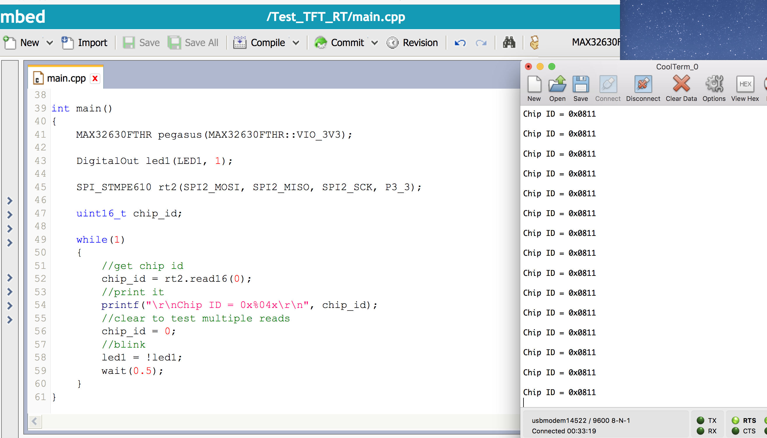
Please see simple test here -> https://developer.mbed.org/users/j3/code/Test_TFT_RT/
I had no problem using the referenced library with the Adafruit TFT Wing and the MAX32630FTHR board. Please see image below.

Hello Justin,
thank you very much for your investigation and your sample code !!! But I am not lucky, because my trace output shows with your software again: Chip ID = 0x0000.
Conclusion: The TFT combination works with another board (ARM M0 - Adruino) fine. Trace output is working, too. One test has been to make a loop back SPI TX on RX on the FTHR: This has worked. Now it looks more that one board doesn't like the other one :-) Now I need more time to do further hardware checks and thanks again, because it is good to now the software isn't the problem.
posted by 20 Mar 2017Hello Charly,
Please ensure that either the MAX32630FTHR object is declared globally, or the very first thing you do in main.
MAX32630FTHR pegasus(MAX32630FTHR::VIO_3V3);
Thanks,
posted by 20 Mar 2017Hello Justin,
I have used your example as it is and I know that the "power-supply on" via the external chip is one of the first steps. The funny thing is with your example code there is the same behavior as I have with my own software: I get sometimes for a longer time the id. But if working, no reset or power on will be allowed.
One idea I have got now is that some is running out of specification with both board, especially in case of power-on. Example: TFT and STMPE610 have no hardware reset which the MCU can control with a PIN. Maybe the power-on from the external chip cannot work correctly, if the TFT board has a wrong startup behavior. Finally, I will buy new hardware, if I am not successful.
posted by 21 Mar 2017News from Charly X:
After further investigation I have now the security there is a power-on problem with my boards (combination of MAX32630 and the TFT board). The STMPE610 didn't start proper in SPI mode, if the power is switched on with the MAX14690. This explains why sometimes after power-on I get the chip id and many times not.
I have used different standard software containing unchanged MAX14690 initialization (from MBED and Justin) and with my own bare metal software.
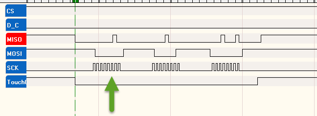
If the chip restart/reset is working I get after the first clock sequence by default and previous software reset the register 0 [reading 0x08]. Increasing the address and writing 0x81 as 2nd value will return 0x08 again and with the next clock sequence I get as expected the 0x11 (both together the chip id 0x0811)
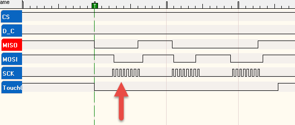
(Note: In the pictures below CS and D_C shall be ingnored.)

The following shows the result in 99% of all power-on cases:

Zero flat line on MISO in case of power-on (STMPE610 ignores SPI).
As work-a-round after MAX14690 power-on on L3OUT: stop in debugger, switch-off and on manually the 3.3V power of the display board and everything is working fine afterwards, but this will never be the final solution :-)
posted by 25 Mar 2017
Charly,
Let me dig into this Wing and thanks for the additional info. It may take me a couple days to get things working as I haven't used this Wing before, but I will be getting back to you.
I guess my previous response should have been a comment instead of an answer, I am still getting used to using this forum, so sorry for any confusion in posts.
Thanks
posted by Justin Jordan 18 Mar 2017