Important changes to forums and questions
All forums and questions are now archived. To start a new conversation or read the latest updates go to forums.mbed.com.
8 years, 11 months ago.
Does mbed compiler can program these?
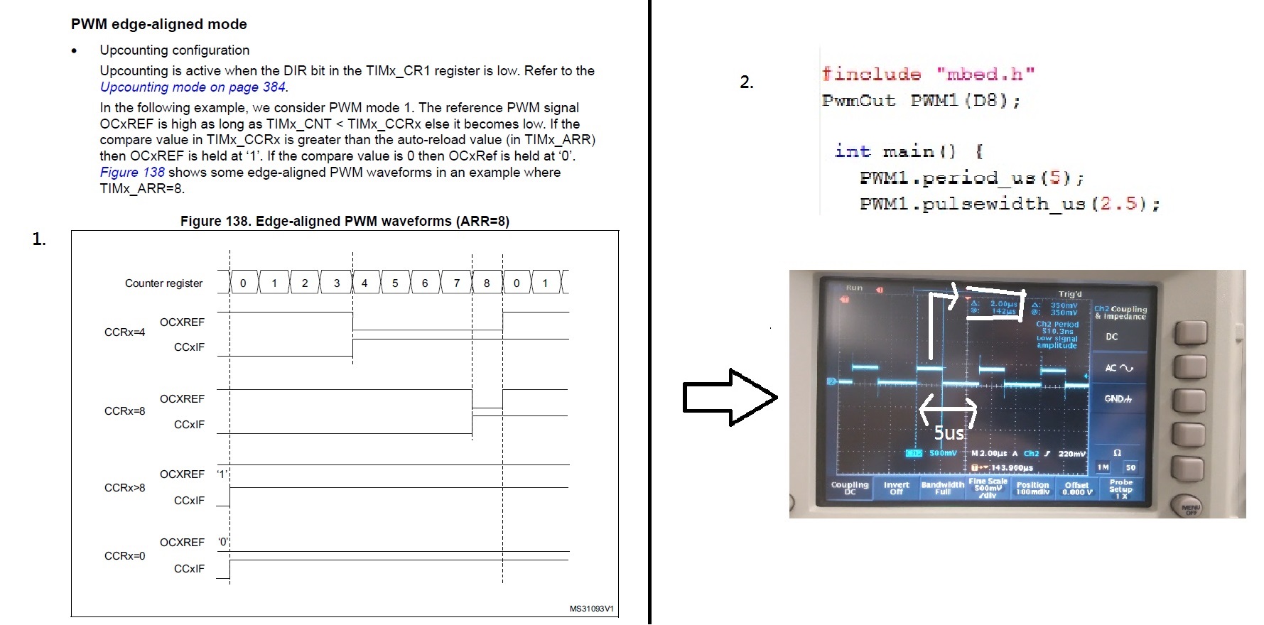
Hi, I have two problems about mbed compiler here. 1. Can I use compiler toset up the CCxIF(image 1, basic on PWM mode of stm32f334xx reference manual)? I want to use for invert my PWM. 2. I use PwmOut function to output PWM as you see as image 2. But the peak time only has 2us as you see as image 2. I also set up other peak time and find that all peak time are only become digit before the decimal point (3.5us to be 3us, 4.3us to be 4us). How can I output the peak time include the digit after decimal point? Please give me answers, thank you. 
1 Answer
8 years, 11 months ago.
Hi,
You can use the FastPWM https://developer.mbed.org/users/Sissors/code/FastPWM/ library to get non-integer microsecond pulses. If you are only using channel 1 and 2 on STM32 you can directly modify the registers to change the polarity.
add this to the initFastPWM definition
PWM_TIMER->CCER =TIM_CCER_CC1P; // invert polarity on channel 1
PWM_TIMER->CCER |= TIM_CCER_CC1E; //enable channel 1
PWM_TIMER->CCER |= TIM_CCER_CC2E; //enable channel 2
Hi so k, I don't have the answer but if you check the documentation for pwmout https://developer.mbed.org/handbook/PwmOut you see that pulsewidth_us takes an int value. This explains picture 2 I think. Perhaps someone else can help with the rest of the question.
posted by Ian Kilburn 22 Feb 2017I am sorry that I forget to write that I also use 'int' for pulsewidth_us function and 'float' for pulsewidth function,but they also same as image 2 (to be a value that digit before the decimal point).
posted by so k 23 Feb 2017Hi so k, the pwmout function has that limitation. The function is limited to int values so your float is truncated. Have you looked at the library FastPWM? https://developer.mbed.org/users/Sissors/code/FastPWM/ You might need to make your own version to support your board. You could also make a change in your new library to set the polarity of the PWM. I think you should be able to use the STM HAL functions for that. I hope this helps.
posted by Ian Kilburn 23 Feb 2017ok, let go back to question1, I see that there is a 'FastPWM_STM_TIM_PinOut.cpp' in the Device of FastPWM, and I see that there is some code for set PWM to channels. Can I change the codes here to make a invert PWM (like make a invert '!'function here)? Since I only need one channel for PWM inverting. If it is possible, can you tell me that how to change? Thank you.
posted by so k 23 Feb 2017Hi so k,
To modify the pinout file look at the alternative function of the GPIO pins in the data sheet in table 13. http://www.st.com/content/ccc/resource/technical/document/datasheet/d1/cd/3d/18/a2/2c/4e/d0/DM00097745.pdf/files/DM00097745.pdf/jcr:content/translations/en.DM00097745.pdf
They have the form TIM1_CH1. I have the F030R8 which already works with the library so I can't test this.
Add this to the FastPWM_STM_TIM_PinOut.cpp file
#if defined (TARGET_NUCLEO_F334R8)
__IO uint32_t* getChannel(TIM_TypeDef* pwm, PinName pin) {
    switch (pin) {
        // Channels 1
        case PA_4: case PA_6:  case PB_4: case PB_8: case PB_9: case PB_14: case PC_6: case PB_6: case PB_7:
            return &pwm->CCR1;

        // Channels 2
        case PA_7: case PB_5: case PC_7:
            return &pwm->CCR2;

        // Channels 3
        case PB_0: case PC_8:
            return &pwm->CCR3;

        // Channels 4
        case PC_9:
            return &pwm->CCR4;
    }
    return NULL;
}
#endif
Or something like that. You'll have to check yourself if that works with your board.
As for the polarity I think you need to set the correct bits in the TIMx_CCER register?
I tried this and it seems to be working on my board with PA_6 and PA_7.
Replace this part in the FastPWM_STM_TIM.cpp file
void FastPWM::initFastPWM(void) {
    fast_obj = new fastpwm_struct;
    #if defined(TARGET_STM32F0) || defined (TARGET_STM32F1) || defined (TARGET_STM32L1)
    PWM_CHANNEL = getChannel(PWM_TIMER, _pwm.pin);
    #else
    PWM_CHANNEL = (&PWM_TIMER->CCR1 + _pwm.channel - 1);
    #endif

    // Depending on the timer and the internal bus it is connected to, each STM timer
    // can have a fixed prescaler from the clock, especially the faster devices.
    // In order not to have to hardcode this in, we use knowledge that mbed lib sets
    // default period to 20ms to reverse engineer the prescaler from this.
    uint32_t current_hz = SystemCoreClock / (PWM_TIMER->PSC + 1) / (PWM_TIMER->ARR+1);
    PWM_CLK_PRESCALER = (current_hz + 1) / 50;  //50Hz is magic number it should be, +1 is to handle possible rounding errors in mbed setup

    //Sanity check in case a target does something different
    if ( (PWM_CLK_PRESCALER == 0 ) || (PWM_CLK_PRESCALER > 16)) {
        PWM_CLK_PRESCALER = 1;
    }
    PWM_TIMER->CCER =TIM_CCER_CC1P; // invert polarity on channel 1
    PWM_TIMER->CCER |= TIM_CCER_CC1E; //enable channel 1
    PWM_TIMER->CCER |= TIM_CCER_CC2E; //enable channel 2
    bits = 16;
    //Enable PWM period syncing for glitch free result
    PWM_TIMER->CR1 |= TIM_CR1_ARPE;
}
Hope you can get it working too. Regards Ian
posted by Ian Kilburn 23 Feb 2017That's ok now,thank you!
posted by so k 24 Feb 2017