Important changes to forums and questions
All forums and questions are now archived. To start a new conversation or read the latest updates go to forums.mbed.com.
7 years, 5 months ago.
Logic of PeripheralPins.c
While trying to understand some problems i am having using spi on a custom board based on NucleoF401RE, i turned back to nucleo and found something for which i am not sure anymore. On NucleoF401RE i see printed on board on the right side on pin D10 following text "PWM/CS/D10". So i can use that pin to connect the chip select and this is also working good but looking at the file:
pin D10 (which is PB_6 based on https://developer.mbed.org/platforms/ST-Nucleo-F401RE/) is listed under the arrays PinMap_I2C_SCL, PinMap_PWM and PinMap_UART_TX but is not listed under PinMap_SPI_SSEL. So first question (1) how can this pin be used as chip select, shouldn't it be listed under PinMap_SPI_SSEL to be used as chip select, i.e. it works but why does it work?
That leads me to the second question: (2) if i have a custom board and want to use for example pin PB_12 for AnalogIn than should i add PB_12 to PinMap_ADC array as follows?
PinMap PinMap_ADC[] = {
....
    {PB_12, ADC_1, STM_PIN_DATA_EXT(STM_MODE_ANALOG, GPIO_NOPULL, 0, 0,  0)},
...
}
(3) Should i also remove it from the array where its declared now PinMap_SPI_SSEL?
Thanks for the help.
EDIT
I tried to to build mbed with the following changes in PeripheralPins.c: i commented the line PB_12 in PinMap_SPI_SSEL and added
{PB_12, ADC_1, STM_PIN_DATA_EXT(STM_MODE_ANALOG, GPIO_NOPULL, 0, 19, 0)},
into the PinMap_ADC.
Building mbed worked fine but i still could not use that pin for AnalogIn using the examples under https://developer.mbed.org/handbook/AnalogIn. Should i change anything else or am i in the wrong path?

2 Answers
7 years, 5 months ago.
Regarding question 1: Yes it should probably be added in that list. However take into account it is only used in SPISlave mode. In regular SPI (master) mode just a DigitalOut is used as CS line.
Question 2: No, that list is used because those pins have AnalogIn capabilities. You can add it to the list, but the hardware to run an AnalogIn on that pin simply does not exist. Otherwise every pin would be in the list :).
Hi Erik,
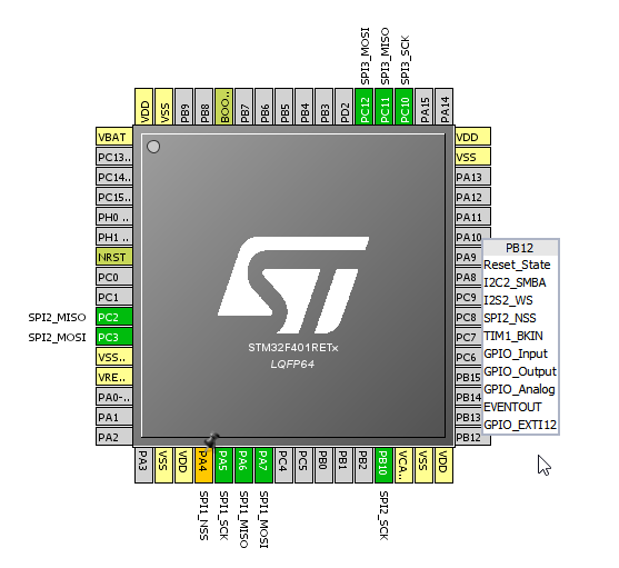
thanks for your response. That is a little bit confusing. Please have a look at the screenshot i am posting. There is the Cortex M4 taken from CubeMX and as you can see the pin PB_12 (on the right side last pin vertically) can be configured to be GPIO_Analog. What am i misunderstanding here?
posted by 10 Nov 20167 years, 5 months ago.
Anteo What you're seeing is that the tools are remaining as generic as possible. MBED correctly set up the pin functions and pin PB12 is not available as an analog pin in the 401RE. However...the control register [GPIO port mode register (GPIOx_MODER)] has a two-bit setting for each GPIO pin which includes "analog". That is what CubeMX is setting when you select that from the pull-down choices.
If you take a look at "Table 8. STM32F401xD/xE pin definitions (continued)" in the 401RE datasheet you'll see that PB12 does not have an analog implementation. That is what Eric is referring to above in his response.
Hope that helps clear up the issue. Bill