Important changes to forums and questions
All forums and questions are now archived. To start a new conversation or read the latest updates go to forums.mbed.com.
7 years, 6 months ago.
TPIC6B595 and solenoid problem
Dear Developers,
I've found a very strange behaviour within a project I'm currently working on. (See solution at the end of the question.)
I'm planning to use a Ti TPIC6B595 shift register to drive a huge bunch of solenoids. Click for the datasheet: http://www.ti.com/lit/ds/symlink/tpic6b595.pdf
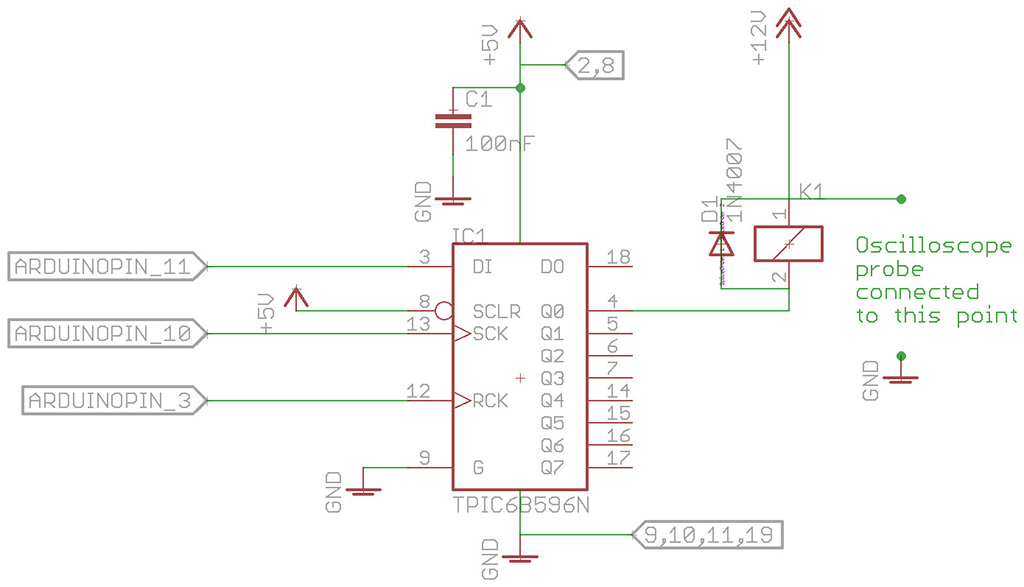
Here is a connection for one solenoid:

All grounds are common. I've used a regulated 12 V constant voltage PS for the solenoid and another 5 V PS for the MCU. +5 is connected to the shift register's pin 5 and 8, meanwhile pins 9, 10, 11, and 19 are all grounded.
The solenoid is a cheap chinese one (I must use almost 1000 individual pieces of them, so price is a keypoint), no datasheet. I've measured 86,8 ohms resistance. The solenoid works fine individually (actuates and deactuates, current draw is around 128 mA on a 12 V PS, voltage drop down to 11.7 (around 330 mV, to be extremly precise). The MCU works fine individually connected to the shift register, which turns on and off a pattern of LEDs in a simple order. One on cycle is 500 ms, each cycle ends with "all ports off command".
When I connect the solenoid "+" side to the 12 V source, the following happen:

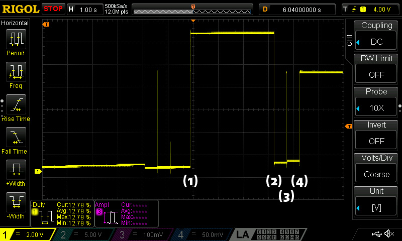
At (1) 12 V PS turned on. At (2) the shift register activates the solenoid. At (3), the "all ports off command" temporarily disabling the solenoid, which goes back to activated state within a few ms due to a new activation command. At (4) the solenoid port is deactivated for a long time.
The problem is: when the port deactivates, the solenoid remains in closed position, the current draw drops, as well as the voltage (aruond 8.3 V), at the same time the shift register stops working properly. The pin of the solenoid can be easily pushed back to its normal state, but this act doesn't take any effect of the situation. The only solution I've found yet is to turn off and back on the 12 V source.
I've asked the very same question on a different board, and based on all the suggestions, I've tested many power sources (two PC ATX PS, constant voltage LED driver PS, multifunction 2 A regulated PS), with more or less the same results.
Any hints and suggestions are welcome. I'm now totally lost (oddly that TPIC6B595 is designd for direct solenoid drive).
Thanks in advance,
Tamás
SOLUTION
The cause of the problem were stupid as hell: the datasheet tells "Related end equipment [...] Automotive Relay or Solenoids Drivers", which could be easily misunderstanable. Literally, this device is not for direct drive of solenoids (inductive loads), instead driving solenoid drivers.
So, the final solution were plain simple: 74HC595 shift registers and ULN2804 darlington arrays. Darlington can support 500 mA on each channel, and works without any problem with all the solenoids actuated at the same time at 33% duty cycle without any problem, including even the smallest rise of temperature.
Here is the final prototype: https://www.dropbox.com/s/50xnamzi6y8v55f/2016-11-05%2018.55.57.mp4?dl=0
1 Answer
7 years, 6 months ago.
Looks like you are measuring the 12V directly on the powersupply pin. A drop to 0V when the solenoid is activated seems to indicate a short circuit or severe overload. The PSU would probably limit the output voltage later on (8V ?) and needs to be cycled before it returns to 12V. Check the D1 protection diode. Maybe it is reversed (or damaged) and shorts the powersupply when you activate the relay.. Also note that most PC ATX PSUs only regulate on the 5V output. The 12V and other outputs are following. The 5V output usually does not regulate well when it is not loaded adequately. Add a powerresistor to make sure you draw enough current on 5V otherwise the 12V could collapse when loaded. The TPIC may also stop working in case of a PSU or output driver overload. The 5V power could be gone and/or the internal protection circuit (500 mA) on the outputs may disable the device until recycled.
Dear Wim, First, thanks for your answer. I've learnt a few new things today. Yes, you've cached one mistake in my description: it's possible that I've used a different measurement process. By the way, all new measurements taken as shown in the schematics shows the same result. Today I've made a new setup with a dummy load similar to the solenoid (overall resistance, final current draw), and it worked out fine (except it's just a resistive load without inductance). Now I'm looking to a well regulated, well built quality PSU, which may be used later in the final project. (Meanwhile it's logical to have a good bench PSU, it's not too clever to use one for production purposes). Anyway, any further hint, suggestion or idea are warmly welcome! Thanks, Tamás
posted by 21 Oct 2016
Hello Tamás, Nice job. Since you'll need 120 of them consider to use ULN2803 (designed for TTL and 5.0 V CMOS). They are much cheaper than ULN2804 (about 14$/100pcs vs 60$/100pcs on eBay).
posted by Zoltan Hudak 06 Nov 2016You're right, Zoltan, thanks for the prompt idea. I'm using 2803 (04 are for higher switch voltage). :-D
posted by Tamas Szekffy 06 Nov 2016ULN2003 is even cheaper (just about $5.50/100pcs). But instead of eight it's equipped with seven outputs with total emitter-terminal current 2.5A.
posted by Zoltan Hudak 06 Nov 2016Yep, it's true. For this purpose, 2803 seems to be far enough, and yet better to build. 30 outputs/sheet: 4 SR and 4 darlington arrays... With 2003, it should be 5, with a somewhat more complicated routing. By the way, thanks for the note. :-)
posted by Tamas Szekffy 06 Nov 2016Hi Tamas, I think the conclusion that the device is not suitable for relays is not correct. Referring to the datasheet section 8.1 Overview:
"The TPIC6B595 device is a monolithic, high-voltage, medium-current power 8-bit shift register designed for use in systems that require relatively high load power. The device contains a built-in voltage clamp on the outputs for inductive transient protection, so it can also drive relays, solenoids, and other medium-current or high-voltage loads."
So the datasheet explicitly mentions relays etc.
I don't have one on hand so cant test its behaviour. The only issue I see is in table 6.3 where is states that VIH High-level input voltage = 0.85*VCC. That means that the typical 3V3 outputs of an mbed is below spec and perhaps transients on the supply voltage cause problems when a relay is activated. Anyhow, good to hear that the alternative solution with a separate shift register and driver seems to work OK.
posted by Wim Huiskamp 06 Nov 2016Dear Wim,
It's literally very hard to imagine a simpler solenoid that I've used for testing. And only one of those over 900 in the final product. I've experienced sever temperature rise, which can be supposed based on the design rules in the datasheet, but it was really extreme. ULN2803 drives 8 of these solenoids at 1 A without any noticable rise of temperature. Logic wasn't the problem (I've tried to drive leds with almost the same load, and there were no problem with it).
Well, I have a set of the SRs now, so I'll make some further tests in different projects in the future.
Thanks for your attention and hints. I've followed you here. :-)
Tamás
posted by Tamas Szekffy 07 Nov 2016