Important changes to forums and questions
All forums and questions are now archived. To start a new conversation or read the latest updates go to forums.mbed.com.
9 years, 3 months ago.
how to open function?
Serial pc(PA_2, PA_3); DigitalOut myled(LED1);
I want open digitalout defintion ..where i can see?,acuatlly iam emebedded c developer.
1 Answer
9 years, 3 months ago.
Hello Sudhir,
To see the documentation available in the on-line compiler hold down the CTRL key and then click on the DigitalOut text in the editor. A local popup window shall open. In the popup window click on the second icon. Then you can release the CTRL key.
mbed library sources are available at THIS link. In api folder click on the DigitalOut.h to see the implementation of DigitalOut class.
NOTE: There is no DigitalOut.cpp (or DigitalOut.c) file. The class is completely defined in the header file.
If you would like to modify the implementation of DigitalOut (or anything else implemented in the mbed library) then you have to replace the mbed library with the mbed-dev sources in your project.
To import the mbed-dev library into your project please carry out the same steps as for any other library:
- Select your target program
- On the toolbar click on the "Import" button
- Select the "Libraries" tab
- Type mbed-dev into the "Search box" and then click on the "Search" button
- After a while you should see a line with info about the mbed-dev library
- Select that line (by clicking on it) and then click on the "Import!" button located just above the "Search" button.
- Once the mbed-dev library has been imported into your program (it takes a while) remember to delete the original mbed library from it (right click on mbed and select delete...).
- Then try to recompile your project. Because also the mbed-dev sources have to be compiled it will take much longer then usually.
After that you'll be able to modify also the code in the mbed-dev library for your project.
okay Thank you,i have one more doubt what is below rhs side?/ is it pin name? PC_13 = 0x2D, PC_14 = 0x2E, PC_15 = 0x2F, in my datsheet showing (0x2D refers to PB8 ) below datasheet but I am refering this datasheet https://www.google.co.in/url?sa=t&rct=j&q=&esrc=s&source=web&cd=1&cad=rja&uact=8&ved=0ahUKEwiW9ZjExaPPAhVJE5QKHTMNBpYQFggbMAA&url=http%3A%2F%2Fwww.st.com%2Fresource%2Fen%2Fdatasheet%2Fstm32f103tb.pdf&usg=AFQjCNHlLVePmNnxYZsNy0m5JA1B2Pnvog&sig2=vgyusEQ1OaS3ZJhRmzF9rw&bvm=bv.133387755,d.dGo
posted by 22 Sep 2016Hello Sudhir,
If you are referring to the following assignment operator
    DigitalOut& operator= (DigitalOut& rhs) {
        core_util_critical_section_enter();
        write(rhs.read());
        core_util_critical_section_exit();
        return *this;
    }
then rhs is a reference to another DigitalOut object.
The operator is designed to simplify assignments as follows:
Code without using the operator
DigitalOut out1(PC_14);
DigitalOut out2(PC_15);
int  value;

out1 = 1;
value = out1.read();
out2.write(value);
Code simplified by using the assigment operator
DigitalOut out1(PC_14);
DigitalOut out2(PC_15);

out1 = 1;
out2 = out1;
sample of code of yours
#include "mbed.h"
//what is 0x2D is it pin number,but if i check  schematic i cannot found 0X2D pin(its showing different pin name)
PC_13 = 0x2D,
PC_14 = 0x2E,
PC_15 = 0x2F,
Hello,
PinName is a unique identification number assigned to each input-output pin. It's used for mapping physical pins to the target chip's General Purpose Inputs and Outputs (GPIOs) or other interfaces (e.g. USART, I2C, SPI, ...). Mapping is specific for each target and is done in the pinmap.c file. For example, for the NUCLEO-F103RB have a look at https://developer.mbed.org/users/mbed_official/code/mbed-dev/file/30b64687e01f/targets/hal/TARGET_STM/TARGET_STM32F1/pinmap.c
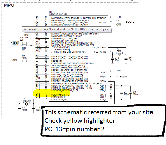
Dear Sir ,I am Referring your code and dev boards is STM2F103C8T6,I have doubt in pin assigment(PinNames.h )and your schematic ...for me both are not matching.
STM32F103C8T6_Hello Project
#include "mbed.h"
//in main.cpp code you mentioned
DigitalOut  myled(LED1);
//this one Iam not understood LED1 is PC_13 its value is 0x2D ,
//but in your schematic 0x2D  Reffers to PB_8
//https://developer.mbed.org/media/uploads/hudakz/stm32f103c8t6_schematic.png
//in schematic PC_13 is in 2nd Pin

Hello, As you can see in the Data Sheet there are STM32F103xx chips available in variety of packages (page 21 through 27). For some of them there are even no pin numbers indicated but rather coordinates (page 21, 23, 25). In addition, even when pin numbers are indicated, the same logical pin (e.g. PC_13) is available at different pin numbers on different packages. To cope with this issue, for a given platform, mbed always assigns the same identification number to the same logical pin (e.g. PC_13 = 0x2D for STM32F103xx) regardless the chip's package. This ID number has nothing to do with (does not equal to) a pin number on a specific package. The best prove could be to run the program and see whether the correct LED is blinking.
posted by 25 Sep 2016