Important changes to forums and questions
All forums and questions are now archived. To start a new conversation or read the latest updates go to forums.mbed.com.
9 years, 4 months ago.
stlinkv2 and stlink utility and stm32f103c8t6 interfcae
Hi guys I am unable to connect stilink utitility software with stlink v2 (swd)..here scree shot http://imgur.com/DU25qi2
Please help me , thank you in advance sudhir
1 Answer
9 years, 4 months ago.
Hello Sudhir,
Have you installed the ST-LINK/V2 driver onto your PC? If not yet then follow this LINK for all details. For optimum performances, ensure that the Nucleo ST-LINK/V2 firmware is upgraded to the latest version. Follow this LINK for all details. Also make sure that only one ST-Link programmer is connected to your PC at a time. (Disconnect your NUCLEO board from the PC before connecting the ST-Link dongle). In the Windows Device Manager check the Universal Serial Bus Devices. You shall see your ST-Link dongle listed.
If you already own a NUCLEO board equipped with ST-LINK/V2-1 programmer then you do not need to use the STM32 ST-Link utility (and a ST-Link V2 Programming Unit / Downloader). Instead you can use the NUCLEO virtual disk to program the STM32F103C8T6 board (drag and drop programming). For more details have a look at the STM32F103C8T6 board section Programming the STM32F103C8T6 board.
Dear Sir,
I am Thankfull to you for your patience to answer my questions,Actually I want connect only STM32F103C8T6 and stlinkv2 swd cable and stlink-v2 utitily software(I have this board only in my house),and Iam succesfullly connected my stm32board to stlink utility.
I want to blink one led in stm32f103c8t6 .
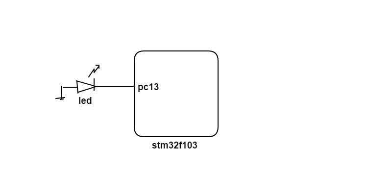
shall i connect led like below passion
gnd  -> green led ->pc13 pin (stm32f103)
Thank you in advance. sudhir acharya
posted by 15 Sep 2016Hello Sudhir,
Now that you have successfully connected your ST-Link V2 SWD programmer to the board you can easily download programs to it. Good news is that one of the LEDs you can see on the board has been already connected to pin PC_13 through a resistor by the board's manufacturer. So please do not connect another one to it. To blink that (on-board) LED click on THIS link. It will start loading the STM32F103C8T6_Hello program into your mbed on-line compiler. When you are asked to confirm it, proceed with clicking on the "Import" button. Once the program has been loaded click on the "Compile" button on the toolbar and then save the generated binary file into a folder of your choice on your local hard drive. Run the "STM32 Link utility" program and open the downloaded binary file. Then click on the "Program verify" button on the tool bar. A popup window shall open. Click on the "Start" button and wait until the binary is completely downloaded to the board. Then press and release the "Reset" button on the board and then you should see the blue LED blinking. If you would like to connect an external LED to another pin (e.g. PC_15) then it shall be oriented just in opposite way to what is shown in your picture above and also make sure to connect a 470 Ohm resistor between the LED and the selected pin to restrict the current drained from that pin below a safe limit in order not to damage the chip. Also remember to modify the program's source code accordingly (replace LED1 with PC_15) before compiling and downloading to the board. Keep in mind that after downloading a binary to your PC you always have to (re)open it in the STM32 Link utility program before downloading to the board. Otherwise you will keep downloading the previous binary to the board's flash.
Acuatlly iam Emdedded c developer, how to open DigitalOut myled(LED1) defination for more understanding..
posted by sudhir acharya 21 Sep 2016Hello Sudhir,
posted by Zoltan Hudak 21 Sep 2016mbed source files are available at THIS link. In api folder click on the DigitalOut.h for more understanding how it is implemented.