Important changes to forums and questions
All forums and questions are now archived. To start a new conversation or read the latest updates go to forums.mbed.com.
11 years ago.
What is wrong with the I2C bus on mBed?
I am using an mBed to communicate with the MCP3428 Chip on the I2C Bus. Here is a code snippet for this communication:
- include "mbed.h"
I2C i2c(p9, p10);
int main() {
while(1) { char configReg [2];
configReg[0] = 0x00; Need to get the acknowledgement from the MCP3428 configReg[1] = 0x00; These are temporary values
i2c.write(i2cAddr, configReg, 1); wait (0.5);
} }
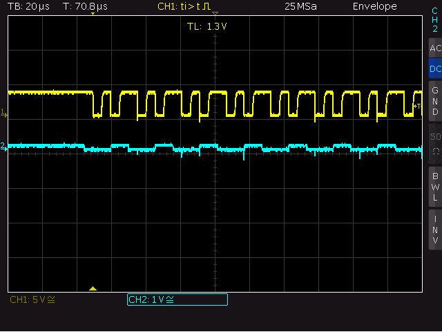
When I run this program on my mBed, I get this waveform on the I2C Bus. (which is clearly messed up).

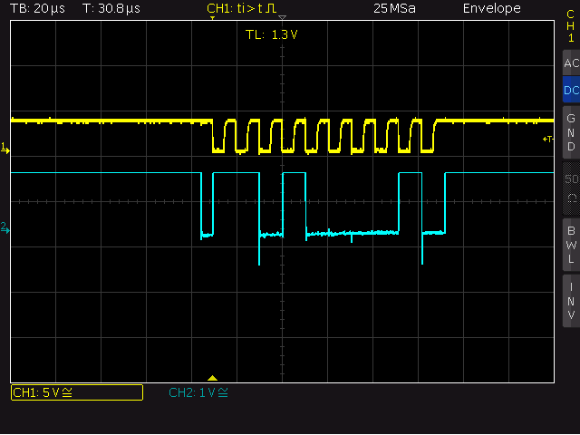
But when I run the same code on a friend's mBed on the same circuit i get the correct waveform.

Does this mean that some component on my mBed is busted? Is there a solution to fix this: other changing my mBed? What could be the cause of this?
2 Answers
11 years ago.
missing pull-up on SDA? short circuit on SDA?
There are Pull-up resistors on SDA and SCL, I have checked for short circuits (there are none), still no luck fixing it.
Also if you look at my clock waveform, it doesn't really look like a clock signal.
posted by 27 Mar 201311 years ago.
Maybe the SDA or SCL pin is not shorted to GND or VCC but shorted to another (active) pin. That will give strange results. Has the I2C bus on p9/p10 ever worked OK in the past? Perhaps some stray piece of wire or solder is touching the cpu pins. Is your GND connection OK.
Also noticed in your second trace that the slave device does not ack your address (1101 0000). Guess the MCP3428 was not connected or using another address in that case.
I have checked and rechecked the circuit, the I2C pins p9/10 are not connected to any other active pins. They are pulled-up to 3V3 of the mBed via pull-up resistors of 5k on each of the pins (I2C connection speed is 100kHz) and directly connected to the Oscilloscope probes. The I2C bus on p9/10 was working perfectly until last week. I configured a CAN on p30/29 to communicate with a second mBed. Both the buses were working fine until weekend. Come Monday, there was no response from the I2C slave device. That is when I noticed the I2C bus throwing this bizarre waveform. I removed the CAN (hardware and software) but still no change on the I2C bus at p9/10.
There is no acknowledgement from MCP3428 on the waveforms as I had disconnected it(for both cases).
posted by 28 Mar 2013