Important changes to forums and questions
All forums and questions are now archived. To start a new conversation or read the latest updates go to forums.mbed.com.
10 years, 9 months ago. This question has been closed. Reason: Unclear question
LPC1549 Hello world CAN bus
Hi all,
I want to communicate a pair of LPC1549 with a CAN bus. I have written a test program but I don't get a successful communication. This is the schematic:

And this is the code of both LPC1549.
Test program CAN bus
#include "mbed.h"
#define TD P0_18
#define RD P0_13
#define PINLED P0_25
#define testRX P0_14
#define testTX P0_15

DigitalOut led(PINLED);
CAN can(TD,RD);
Serial uart0(testTX,testRX);

int main() {
	uart0.baud(38400);


    while(1) {
//--Un/comment for transmitter / receiver
//#define TRANSMITTER
#ifdef TRANSMITTER

    	const char dat = 'B';
        int msg_id = 1010;
    	CANMessage m(msg_id,&dat,1);
    	if(can.write(m)) uart0.printf("Send: %s \n\r",m.data);
    	else uart0.printf("Fail sending CANMessage");

#else

    	CANMessage msg;
    	if(can.read(msg)) uart0.printf("Read: %s \n", msg.data);
    	else uart0.printf("Nothing read \n\r");

#endif
    	led = !led;
        wait(0.2);
    }
}
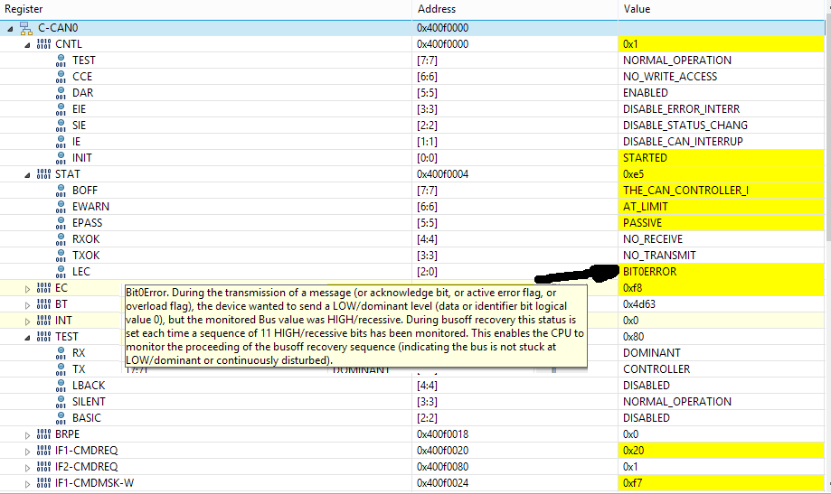
This is the state of registers after write commnad:

Someone knows what is the problem?
1 Answer
10 years, 9 months ago.
Hi,
In this platform, P0_18 and P0_13 are connected to mbed interface chip and I don't recommend to use these pins for CAN TD/RD, because these pins are used for virtual serial port. This is probably not an issue in your test program you provided with.
    // Serial to USB pins
    USBTX = P0_18,
    USBRX = P0_13,

    // snip

#define STDIO_UART_TX     USBTX
#define STDIO_UART_RX     USBRX
I am not sure how do you connect these pins (i.e. physical CAN0_TD and CAN0_RD pins in your schematic) to the CAN transceiver/receiver chip. If you use CAN0_RD and CAN0_TD pins in LPCXpresso header (marked as P2), you need to change SJ4 and SJ5 setting. In that case, please note that you can not use virtual serial port feature in this platform.
http://www.lpcware.com/system/files/LPC1549_LPCXpresso%20v2_schem_Rev_B3.pdf
In mbed SDK porting test, we used D2 and D3 (P0_29 and P0_9) for CAN TD/RD and it passed the test.
https://github.com/mbedmicro/mbed/blob/master/libraries/tests/mbed/can/main.cpp
