Important changes to forums and questions
All forums and questions are now archived. To start a new conversation or read the latest updates go to forums.mbed.com.
11 years ago.
Schematic diagram for LPC1768 and SP485E connection to dynamixel RX-64
Hello,
As mentioned from the title, I would like to ask if anyone have the schematic diagram to connect LPC1768 to SP485E and then to dynamixel RX-64 ?
I am using SP485E to convert the signals from LPC1768 to a 485 serial port.
2 Answers
11 years ago.
/media/uploads/Grag38/capture_d--cran_2015-04-14_-_11.20.38.png /media/uploads/Grag38/capture_d--cran_2015-04-14_-_11.23.35.png
Something like that...
This an usually way of doing things with RS485.
11 years ago.
It doesn't work.
How about this schematic ? Is it correct if I were to use it for LPC 1768 I realise that it uses 2 x 485 chips to split the transmitter and receiver..

Rs485 is half duplex. If you want to use 2*485 together as one receiver and one transmiterit is more like an rs422....
There is no 120 ohm resistor... Mhhh You wrote it does not work... Can you explain more your trouble ? It works for me ! I used it a lot of time and I get 10 485 drivers at home. So from give us your code, your electronic schema and Iwill test it...
Best regards
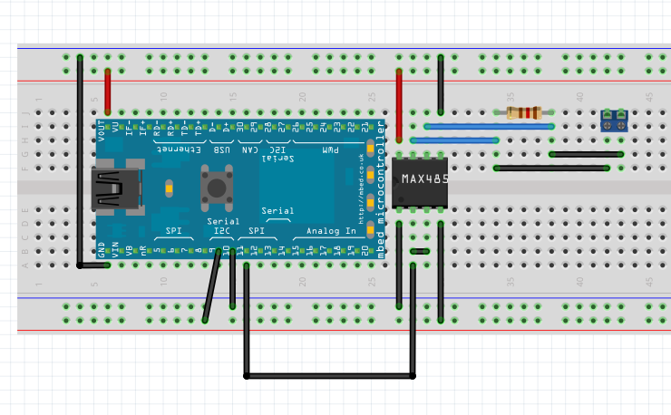
posted by 14 Apr 2015I uses 2 SP485E chip and connect them according to the schematic that I posted. The controller module I used is lpc1768 may be different from the schematic diagram header 16X2 but I connect them accordingly. GND to all the common grounds, 3.3V regulated out aka VOUT is connected to pin 8 of both SP485E. Pin 9 (tx serial) connected to pin4 of the top SP485E. Pin 10 (rx serial) connect to pin 1 of the bottom SP485E. Pin 6 of both SP485E is connected to pin 3 of dynamixel RX-64. Pin 7 of both SP485E is connected to pin 4 of dynamixel RX-64. Pin 1 of dynamixel RX-64 is connected to common ground. Pin 2 of dynamixel is connected to a power supply of 15V and 1A. Mbed is powered up via USB from my laptop. The capacitor which is connected between pin 8 of the SP485E and ground is not used (my supervisor told me that it is not needed).
The codes I used in mbed is.
- include "mbed.h"
- include "MX28.h"
- define MX28_DEBUG
Serial pc(USBTX, USBRX);
MX28 mx28 (p9, p10, 57142);
int main() {
uint8_t servo1ld = 0x01;
while (1) {
mx28.SetMovingSpeed(servo1ld, 100, false);
mx28.SetGoalPosition(servo1ld, 0);
wait (2);
mx28.SetMovingSpeed(servo1ld, 100, false);
mx28.SetGoalPosition(servo1ld, 90);
wait (2);
} }
As for the codes, I am using MX28 library to program my RX-64 motor. Actually for now all I want is to get the motor start moving before I could do the actual programming that I need which is to control the motor shaft rotation from the joystick. Sorry for the presentation of the code due to the 'Post comment' format restrictions.
Thank you for your time
posted by 15 Apr 2015