Important changes to forums and questions
All forums and questions are now archived. To start a new conversation or read the latest updates go to forums.mbed.com.
8 years, 4 months ago.
Trying to use I2C_LCD with K22F base board and 4X20 I2C adapted display
Hi All, I am having a lot of problems figuring out how to go about making I2C/LCD work on my K22F. I am using the provided SDA/SCL signal lines on the K22F. My problem is wrapped around the I2C_LCD library.
I've downloaded the library and it looks like it has a wide variety of options available. When I select an option that seems close to my board configuration the compiler balks and says that it is missing variables that weren't defined. Looking at the documentation that I can find there seems to be a lot of diversity in the library itself which may be adding to the confusion.
I'm still relatively new to MBED so there may be information out there that I'm just not finding.
o Is there a working implementation of I2C_LCD that I can use with a K22F, or do I need to revert to, say - the KL25Z?
o Which library is the "real" library? I.e. what should be my starting point?
o What configuration is likely to work? (i.e. How do I avoid chasing my tail with the assumption that something that works and yet the basic functionality is broke?
I'm sure that once I've gotten the display to say "hello world" I'll be fine - but since I don't have any confidence that my configuration even works I'm just casting around for angles of approach.
Thanks!


Question relating to:
2 Answers
8 years, 4 months ago.
Hi Rich, are you trying to work with my enhanced Textlib?
Settings depend on the type of interface and the type of controller. Please provide more info and check the notebook page. Let me know if you need more help.
The example program TextLCD_HelloWorld2 should also help you to get started:
#include "mbed.h"
#include "TextLCD.h"

// Host PC Communication channels
Serial pc(USBTX, USBRX); // tx, rx

// I2C Communication
I2C i2c_lcd(p9,p10); // SDA, SCL           <== adapt pins for your board


// LCD instantiation for display connected through a PCF8574 I2C expander port
TextLCD_I2C lcd(&i2c_lcd, 0x40, TextLCD::LCD20x4);    // I2C exp: I2C bus, PCF8574 Slaveaddress, LCD Type

int main() {

  pc.printf("TextLCD Enhanced Test. Columns=%d, Rows=%d\n\r", lcd.columns(), lcd.rows());

  for (int row=0; row<lcd.rows(); row++) {
    int col=0;

    pc.printf("MemAddr(Col=%d, Row=%d)=0x%02X\n\r", col, row, lcd.getAddress(col, row));
//    lcd.putc('-');
    lcd.putc('0' + row);

    for (col=1; col<lcd.columns()-1; col++) {
      lcd.putc('*');
    }

    pc.printf("MemAddr(Col=%d, Row=%d)=0x%02X\n\r", col, row, lcd.getAddress(col, row));
    lcd.putc('+');
  }
}
Thanks for the response. I'm trying to use a Freescale K22F board to do this, and I guess I'm not understanding the mappings between arduino and that board.
I've seen "I2C i2c_lcd(p28, p27);" which I presumed to be equivalent to the PTE0, PTE1 on that board as shown by the MBED diagram. I'm getting warnings that the pins have a problem with that mapping so I'm just scratching my head here.
Rich
posted by 07 Dec 2015I dont have the K22 so cant try it out. However, mbed-src PinNames.h and the schematic show that (PTE0, PTE1) are also used as (USBTX, USBRX). This could cause the compiler conflict. The schematic shows that D14, D15 pins are by default not even connected to anything.
// USB Pins
    USBTX = PTE0,
    USBRX = PTE1,

    // Arduino Headers
...
    D14 = PTE0,
    D15 = PTE1,

    I2C_SCL = D15,
    I2C_SDA = D14,

...
    A4 = PTB3,
    A5 = PTB2,
You may want to try (PTB3,PTB2) instead. Note that this I2C port is also used on the board internally for some sensors. It has pull-up Rs onboard.
// I2C Communication
I2C i2c_lcd(PTB3,PTB2); // SDA, SCL           <== adapt pins for your board
Some other valid I2C pins are:
/************I2C***************/
const PinMap PinMap_I2C_SDA[] = {
    {PTB1 , I2C_0 , 2},
    {PTB3 , I2C_0 , 2},
    {PTC11, I2C_1 , 2},
    {PTD3 , I2C_0 , 7},
    {PTD9 , I2C_0 , 2},
    {PTE0 , I2C_1 , 6},
    {PTE25, I2C_0 , 5},
    {NC   , NC   , 0}
};

const PinMap PinMap_I2C_SCL[] = {
    {PTB0 , I2C_0 , 2},
    {PTB2 , I2C_0 , 2},
    {PTC10, I2C_1 , 2},
    {PTD2 , I2C_0 , 7},
    {PTD8 , I2C_0 , 2},
    {PTE1 , I2C_1 , 6},
    {PTE24, I2C_0 , 5},
    {NC   , NC   , 0}
};
Wim,
I've moved things over to PTB3 and PTB2. The routine provided run's its test but no output from the LCD (20X4). The three address lands are open and so I'm assuming the address is 0x27. The code provided shows the address as being 0x42. My i2c chip is a pcf8574T.
Rich
posted by 07 Dec 2015The I2C slave address for the mbed libs are shifted left by one bit compared to the Arduino I2C slaveaddress convention. So when all addresspins are open the correct address is either 0x40 or 0x4E.
// LCD instantiation for display connected through a PCF8574 I2C expander port
TextLCD_I2C lcd(&i2c_lcd, 0x40, TextLCD::LCD20x4);    // I2C exp: I2C bus, PCF8574 Slaveaddress, LCD Type
or
TextLCD_I2C lcd(&i2c_lcd, 0x4E, TextLCD::LCD20x4); // I2C exp: I2C bus, PCF8574 Slaveaddress, LCD Type
Also make sure you have the correct I2C expander hardware selected that matches yours otherwise the port pin mapping between the PCF8574 and the LCD wont be correct. The correct hardware is selected in TextLCD_Config.h For example
//Select Serial Port Expander Hardware module (one option only)
#define LCM1602     1
Check the notebook page for details.
I assume you already see line 1 and 3 as all black squares on the LCD when power is on and contrast is set correctly?
posted by 07 Dec 2015Wim,
Yes, I see black squares as you have dscribed.
I have set "I2C i2c_lcd(PTB3,PTB2); SDA, SCL" and wired those pins (A5, A4) to the SCL,SDA pins going to the LCD Serial adaptor.
if I set the serial port expander to LCM1602 there are a bunch of compilation errors. If I leave it at "default" the compiler is happy.
I have used codes of 40, 70 as id numbers. No joy there.
It doesn't seem to be communicating at all.The display is the 1602 type of 4 line display from eBay. Same with the I2C modules.
Sorry to be a pain :)
Rich
posted by 07 Dec 2015Note that only one option must be enabled. So when you select LCM1602 as 1, then DEFAULT (and all others) must be set at 0.
//Select Serial Port Expander Hardware module (one option only)
#define DEFAULT    0
#define LCM1602     1
The slave address must be either 0x40 or 0x4E as stated above.
posted by 07 Dec 2015ID 0x4e causes the display to go dark and there are what look like weird graphical characters displayed. I suspect this is part of the scan routine that is done by the routine lcd_helloworld2.
Some progress, at least I can address the i2c interface.
Rich
posted by 07 Dec 2015Turned off the default but MBED doesn't like LCM1602.
I'll try it again just in case.
Rich
posted by 07 Dec 2015Wim, Setting "#define LCM1602 1" causes the compiler to return:
Identifier "D_LCD_PIN_E" is undefined <then some other stuff> Identifier "D_LCD_PIN_E2" is undefined.... etc.
posted by 07 Dec 2015The D_LCD undefined compiler problem sounds like an old version of the lib. The last version number in the header of TexTLCD_Config.h should say: 2015, v09 Make sure the TextLCD lib is up to date (right click on the lib in your project and select update). Note that you will lose any changes you made in the lib source code.
The display should show 0, 1, 2, 3 at the start of each line, the rest of the line is filled with * and the right most character should show a +.
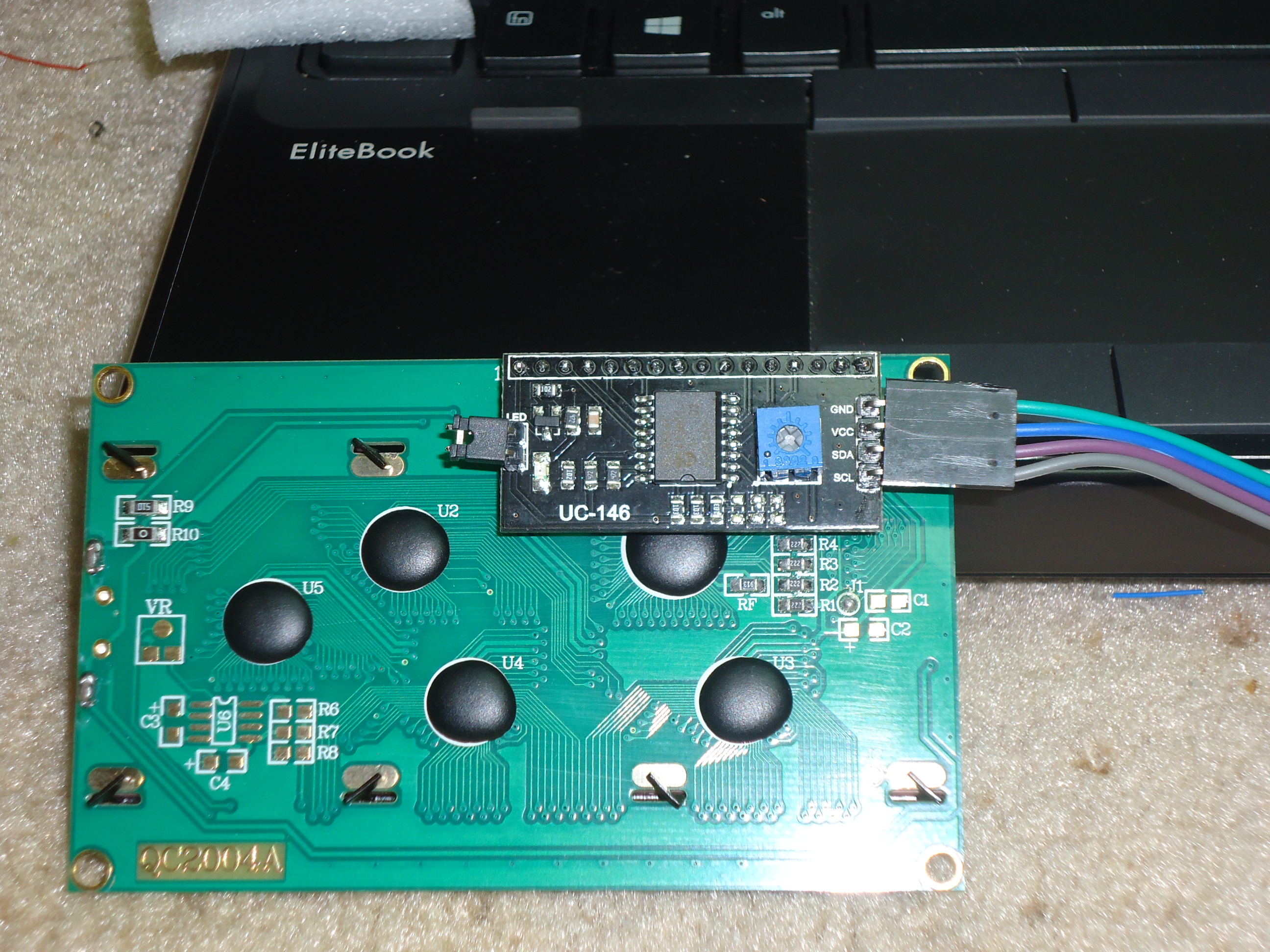
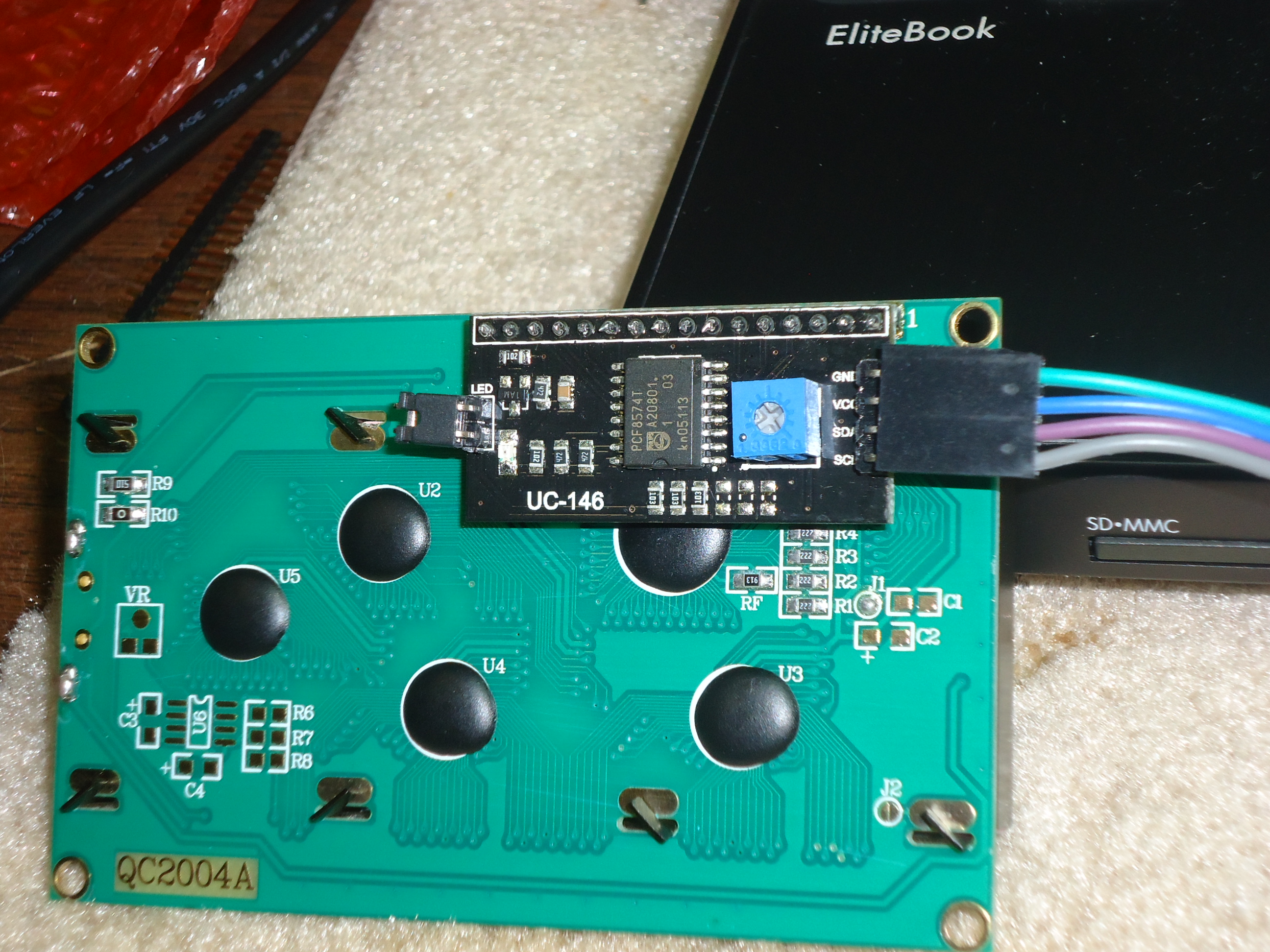
Can you post a picture of your I2C portexpander. Maybe it is a different type (eg DFROBOT). Also make sure all pins are connected correctly. Perhaps one is not making contact with the LCD.
posted by 07 Dec 2015OK, looks like yet another clone of the LCM1602, the DFROBOT setting should also do it. They have the same pinmappings. Make sure you update the TextLCD lib as stated above. The undefined error for LCM1602 hints at an older temporary version of the Lib that had the LCM1602 define only as a placeholder.
posted by 07 Dec 2015I did an update of the library and it seems to have fixed it. However, my backlight is shut off when this runs. I'm looking at the manual, but you could save me a moment if you could point me at the call to turn on the backlight.
lcd.LightOn() ? lcd.Backlight().LightOn;? :)
posted by 07 Dec 2015OK, almost there!
Try this
lcd.setBacklight(TextLCD::LightOn);  // Backlight On

wait(1);

lcd.setBacklight(TextLCD::LightOff);  // Backlight Off
8 years, 4 months ago.
This would be a good place to get started with a LCD like that. https://developer.mbed.org/components/HD44780-Text-LCD/